Continue to Site

Welcome to EDAboard.com

Welcome to our site! EDAboard.com is an international Electronics Discussion Forum focused on EDA software, circuits, schematics, books, theory, papers, asic, pld, 8051, DSP, Network, RF, Analog Design, PCB, Service Manuals... and a whole lot more! To participate you need to register. Registration is free. Click here to register now.

6v-12v AC/DC to 5v regulated DC <100mA, the easy way?

Status
Not open for further replies.

neazoi

Advanced Member level 6
Joined
Jan 5, 2008
Messages
4,119
Helped
13
Reputation
26
Reaction score
15
Trophy points
1,318
Location
Greece
Activity points
36,918
Hi,
I want to convert a 6v-12v AC or DC source (both needed) to 5v stabilized DC <100mA.
The obvious way is to use a bridge rectifier, followed by a 78L05.
However, the bridge and the regulator is not an LDO, so I believe that there could be a problem converting from 6v to 5v.
I would like to use the simplest solution with common parts (not special ICs) and no switching regulators, due to RF noise concerns.
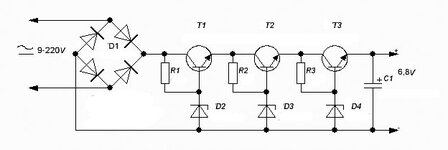
 

Hi,

using 6V DC as input to an 78L05 is no good idea.
According TI "LM78Lxx" datasheet the input voltage should be at least 6.7V

Using 6V AC should work.
6V AC means +/- 6*sqrt(2) = +/- 8.48V
even if you use full wave rectifier you should be above 6.7V.

In detail it depends on true peak voltage which depends on
* output_voltage vs load_current of transformer
* mains voltage
* diode drop
* capacitor ripple voltage

Mind the increased RMS current when using rectifiers. You can´t draw 100mA DC from a 100mA AC rated transformer.

Klaus
 

    neazoi

    Points: 2
    Helpful Answer Positive Rating
Hi,

using 6V DC as input to an 78L05 is no good idea.
According TI "LM78Lxx" datasheet the input voltage should be at least 6.7V

Using 6V AC should work.
6V AC means +/- 6*sqrt(2) = +/- 8.48V
even if you use full wave rectifier you should be above 6.7V.

In detail it depends on true peak voltage which depends on
* output_voltage vs load_current of transformer
* mains voltage
* diode drop
* capacitor ripple voltage

Mind the increased RMS current when using rectifiers. You can´t draw 100mA DC from a 100mA AC rated transformer.

Klaus
Thanks!
This is to be placed inside old tube radios, directly fed from the tube socket filaments.
I believe that all these radios had AC on their filaments and not DC.

But how would you do it, if you were not allowed to use a switching regulator?
This time, I would allow SMD regulators as a requirement for the circuit, if they are LDO and easy to connect like the 78xx series.
 
Last edited:

Hi,

difficult to answer. I´m not experienced with tubes.

Please have in mind: The rectifiers will distort the sine. Overtones / switching noise will be the result.
So if the same voltage is applied to the tubes, you have to ensure that this does not harm the tube´s operation or the sound.

Thus I´d look for less critical power source.
If DC in the range of 7V ... 20V exists then use it to power the 7805.

Also mind: Even if the 78L05 is rated with 100mA .. this does not mean you can simply use it. You still have to care about power dissipation.
Example: When you use a 78L05 in TO-92 package you should not use an input voltage higher than 7.2V when you want it to stay below 60°C.
(T_amb = 25°C, R_TH_JA = 160K/W, 100mA)
--> Ptot = (60°C - 25°C) / 160°C/W = 0,22W ... which means 2.2V + 5V = 7.2V

So when using 20V input and a 78M05 in TO-220 package you have to expect 60°C. Better use a heatsink.

Mind to use caramics capacitors close to the 7805 legs, both input and output to GND.

Klaus
 

    neazoi

    Points: 2
    Helpful Answer Positive Rating
Hi,

difficult to answer. I´m not experienced with tubes.

Please have in mind: The rectifiers will distort the sine. Overtones / switching noise will be the result.
So if the same voltage is applied to the tubes, you have to ensure that this does not harm the tube´s operation or the sound.

Thus I´d look for less critical power source.
If DC in the range of 7V ... 20V exists then use it to power the 7805.

Also mind: Even if the 78L05 is rated with 100mA .. this does not mean you can simply use it. You still have to care about power dissipation.
Example: When you use a 78L05 in TO-92 package you should not use an input voltage higher than 7.2V when you want it to stay below 60°C.
(T_amb = 25°C, R_TH_JA = 160K/W, 100mA)
--> Ptot = (60°C - 25°C) / 160°C/W = 0,22W ... which means 2.2V + 5V = 7.2V

So when using 20V input and a 78M05 in TO-220 package you have to expect 60°C. Better use a heatsink.

Mind to use caramics capacitors close to the 7805 legs, both input and output to GND.

Klaus
That's true, many of these sets use directly heated tubes. This means that if you take the power directly from the filaments you may distort the signals or worse, completely change the directly heated cathode bias to the point that the radio do not work anymore.

This leaves only one option. take the voltage out of the anode.
Because the anode is always at positive DC, you do not have any diodes in the path.
However this means that you have to convert a high voltage with a range that can be anything from 100-600v unregulated DC, down to 5v regulated DC at 100mA. This is tough, isn't it?
 

Hi,

as said: I`m not experienced with tubes, thus I can´t say whether this is critical or not.
I just wanted to inform you about this possible problem.

****
Using 100V or more is no usful way.

****
What about using an additional mains driven transformer just for the 5V supply.
(I think I´ve some unused ones in my stock.)
-->use 6V...9V AC rated for at least 200mA

Klaus
 

    neazoi

    Points: 2
    Helpful Answer Positive Rating
That's true, many of these sets use directly heated tubes.
Don't think so. There are very few tubes using direct heating, e.g. so called electrometer tubes, none of them is used in receivers.

Nevertheless the heating supply has sometimes a grounded center tap or a wire wound potentiometer to adjust the ground potential, mainly to zero 50 Hz crosstalk to the audio signal.
 

    neazoi

    Points: 2
    Helpful Answer Positive Rating
Hi,

as said: I`m not experienced with tubes, thus I can´t say whether this is critical or not.
I just wanted to inform you about this possible problem.

****
Using 100V or more is no usful way.

****
What about using an additional mains driven transformer just for the 5V supply.
(I think I´ve some unused ones in my stock.)
-->use 6V...9V AC rated for at least 200mA

Klaus
Yes, this is obvious, but The whole circuit must fit inside an octal socket tube (just to give an estimation of the size) so using a transformer is not good due to size constrains.
--- Updated ---

Don't think so. There are very few tubes using direct heating, e.g. so called electrometer tubes, none of them is used in receivers.

Nevertheless the heating supply has sometimes a grounded center tap or a wire wound potentiometer to adjust the ground potential, mainly to zero 50 Hz crosstalk to the audio signal.
This is a good technique, I have asked about this a few years ago in this forum.
Are you sure about the directly heated sets?
Maybe I should ask someone that repairs these old 40's radios, to find out the percentage that used directly heated tubes compared to the non-directly heated.
 

Maybe I'm talking nonsense here but if the intention is to 'modernize' an ancient vacuum tubed radio and the problem is to generate the new voltages required, why not just replace all the tubes with FET equivalents and run everything off low voltage?

Brian.
 

Maybe I'm talking nonsense here but if the intention is to 'modernize' an ancient vacuum tubed radio and the problem is to generate the new voltages required, why not just replace all the tubes with FET equivalents and run everything off low voltage?

Brian.
Hi Brian,
The question is about replacing only one tube with a modern circuit and keep all the rest in the radios as it is. The circuit requires +5v regulated to operate.
It is not intended for a particular radio, else I could look at the schematic. It is more of a general replacement circuit.

If I take the power from the heaters, the problems mentioned above may be present (change the directly heated bias, introduce noise from the circuit rectifiers)
If I take the power from the HV DC line no rectifiers are required, but there has to be a way to convert this HV DC to +5v regulated (<100mA).
Switching converters are to be avoided due to noise leakage inside the old AM radios.

that's a tough one I think...?


Maybe it could be done in 2 or more steps, first somehow convert the 100-500/600v to low unregulated voltage, then use a 7805 regulator for the low voltage regulator. See this example
--- Updated ---
 

Attachments

  • HO4F4.jpg
    HO4F4.jpg
    17.8 KB · Views: 99
Last edited:

You can do it in multiple stages like that but the power dissipation will still be W = (Vin -Vout) * I.
Worst case scenario using your figures is (600 - 5)* 0.1 = 59.5W which is probably more than you can lose without a substantial heat sink or cooling fan. Also consider that the supply line of tubed radios is high voltage but low current, 100mA is possibly more than the entire radio consumes already and could overload the power supply.

If this is to replace a 'magic eye' tube, perhaps using an LCD of some kind to keep current consumption very low might work and let you use a simple resistor/Zener regulator. The target anode of those tubes was only a fraction of one mA.

Brian.
No unfortunately an LCD is not good at all, despite the low consumption. You have a point here, the low HV is of low current, so again there is a wall here I am facing.
Perhaps there is no other solution than taking the power from the heaters, which is also safer and there is plenty of current.

I have checked the most commonly used tubes in radios and they all use indirect heaters. FvM is correct. So I guess taking power from the heaters is just fine.
However, this does not give an indication if a radio has mixed heater type of tubes.

USA mostly 6e5 6g5 6h5 6t5 6u5 1629
Europe mostly EM80 EM81 EM84 EM85 UM80 UM81 AM1 EM1 EM4 EM34 EM35 EFM1 EFM11 EM11 UM11

I bet none of these old radios use DC for their heaters, what do you think?
So I would be able to get 5v marginally with a bridge rectifier and a 7805 from heater voltages of 6-12vAC.
 
Last edited:

I restore/repair shortwave receivers. Most, 95% +, use a filament transformer for filaments.
There are some radios whose filaments are line derived, one such radio in the millions.
"The All American 5" was such a radio. That was AM band, cant remember if also FM band.
These radios widow makers, some with hot chassis at the line V. Love eating the front end of
scopes when user probes them without isolation or differential probing. Tek, Agilent have ap notes on this.

You can get LDOs for 5V with 250 mV dropout.


Regards, Dana.
 

    neazoi

    Points: 2
    Helpful Answer Positive Rating
Back in my father's day I recall reading some bickering
about AC vs DC filament power. AC hum was a concern but
so was cost, back when there weren't rectifiers other than
finned selemium stacks and tube rectifiers (which wanted
cathode heat, so no chicken, no egg). Cost always won, on
anything but the highest-end audio and radios.

Nominal 6.3V filament xfmr windings can be expected to be
pretty sloppy, voltage-wise.

There are many CMOS LDOs now, and some of these have
>12V VIN(max) (at the cost of incremental Ron). A PNP-output
LDO might also serve although saturation could be a stability
challenge at low VIN.

If you want cheap like dirt, why not put the guts of one of
those ubiquitous USB-output wall warts, minus the prongs
and socket, inside the chassis? Inside you'd find as small as
practical a switched-capacitor or magnetic DC-DC with a
tolerably low* noise level, crushed for size and cost (but
in the junk box, all is free).

* according to who?
 

The problem with using the heater supply has already been mentioned, you can't assume one side of the supply is ground, it could be floating or it could use a pot to try reducing hum or it could use a 'hum bucking' coil in an attempt to induce anti-phase hum.

Perhaps a suitable alternative is to rewire the heaters to use DC then ground one side. That eliminates the hum by keeping AC out of the wiring and gives you a low voltage supply at the same time. As above, the reason this wasn't a viable solution in the past was that high current rated diodes didn't exist and rectifying several hundred mA through a tube would be too costly.

Question: what does this gadget ultimately produce?

Brian.
This is food for thought for a device to be used as a drop-in replacement for magic eye tubes in these old radios. This is a general use device, not specified for a particular radio. Since these radios extend from LW to SW, I do not want to use a switching regulator inside the chassis. Just unplug the old tube and plug this replacement.

The problem with the heater supply you mention, can't be cured with the use of a bridge rectifier? The AC inputs of the rectifier to go to the filament sockets. Then the + go to the solid state eye and the - to go to the ground of the eye. Will that induce problems with the things you mention above?

Another aproach would be to be able to find a tiny transformer and have forget about all these, but, I think the size would be much bigger than the diameter of the tube body (even for just 100mA) and the cost would be high to release it as a product.

Another problem mentioned and this was for sets that did not use a transformer. It would be prohibitive to use the bridge directly on these I think. To my experience many sets used the series mains heated tubes and just a power resistor for the anodes, not just few.
 

Series heaters will never work in that application, not only because of the potentially high and unpredictable voltages with respect to chassis but because from cold, the filament chain has a high inrush current that needs to be maintained and respected.

The problem as a drop-in replacement is the heater circuits are not wired the same from one model of receiver to the next, some have no chassis connection at all, the heater wires are isolated from all other circuits, some will be grounded on one side but you can't tell which and some have an adjustable ground for hum cancellation. You can guarantee the voltage across the heater pins will be OK but not the potential from each side to chassis. Wiring a bridge could short out part of the circuit and cause damage. The voltages you want to indicate will typically be between cathode and control grid which are both referenced to chassis.

May I ask again, how does your proposed replacement work? Is it a light display using LEDs for example or some meter movement? The solution may be to optimize the current it needs rather than working on a new power supply process.

Brian.
 

    neazoi

    Points: 2
    Helpful Answer Positive Rating
The solution may be to optimize the current it needs rather than working on a new power supply process.

Brian.
Thus, taking the voltage from the anode, and optimize the circuit for low current consumption, is this what you mean?

Do you think that finding a tiny 50Hz transformer (if that thing exists) will solve all the issues with the filament power you mention?
I am thinking that what we actually need here is a small isolation transformer. How about a small common mode choke to be used as such a transformer? We need only small current so this might work. despite of the losses..?
Or maybe a small tiny audio isolation transformer, It might work for the currents we are talking?

All of these of course if a transformer on the heaters can be used without problems.
 
Last edited:

It would have to be a 'real' transformer so probably too big to fit in the tube base.
An alternative idea along the same lines might be to use a bridge rectifier but instead of taking one side of its output to chassis, use it to power a miniature isolated power supply then take the output of that to chassis.

I'm thinking of something like this:

They are quite small but you do still need to ensure the voltage fed into it is fairly stable.

Brian.
 

    neazoi

    Points: 2
    Helpful Answer Positive Rating
A discussion of DC filaments vs AC. Note many posts are Transmitting tube related, but there
is also comments on the receive side. Keep in mind most receivers have uV sensitivities, so
issue is complicated, eg. those parts of signal chain most susceptible.


Regards, Dana.
 

Status
Not open for further replies.

Similar threads

Part and Inventory Search

Welcome to EDABoard.com

Sponsor

Back
Top