Continue to Site

Welcome to EDAboard.com

Welcome to our site! EDAboard.com is an international Electronics Discussion Forum focused on EDA software, circuits, schematics, books, theory, papers, asic, pld, 8051, DSP, Network, RF, Analog Design, PCB, Service Manuals... and a whole lot more! To participate you need to register. Registration is free. Click here to register now.

Is the loop stable in this case? and how to get a transfer function out of a wave?

Status
Not open for further replies.

aburdo

Newbie
Joined
Dec 20, 2021
Messages
5
Helped
0
Reputation
0
Reaction score
0
Trophy points
1
Activity points
52
Hi all,

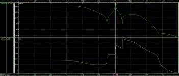
I am wondering how to know if a loop is stable in the case attached. (Loop gain is attached).
As I understand, if I get to a phase of 0 (or 360) with a gain of greater than 1, then the loop won't be stable.
So if I am correct, the example should be unstable, but I just can't make it oscillate.
1. I tried to make the loop oscillate by putting a voltage pulse with different amplitudes and different widths on the loop itself.
2. I tried to push(pull) a current pulse to(from) a high impedance node with different amplitudes and widths.

Nothing makes it oscillate.

Another note: I also want to make a model from this, so I need to get a transfer function out of this PWL.
Any idea how to do so? I tried to use matlab's identification tools box. I am able to get a "model output" (button in the GUI of the tool) with a fit of 99.9%, but if I look at the "frequency response" button, the graph I get is completely different and exporting the transfer function also fit the "frequency response" and not the "model output".
Any idea of what am I doing wrong?
Or any other suggestion of how to get a transfer function out of the graph below?

Thanks a lot everyone
 

Attachments

  • LSTB example.JPG
    LSTB example.JPG
    139.3 KB · Views: 132

My understanding to make an oscillator is you need unity gain as opposed to gain of >1. A gain of 1 will maintain the signal whereas a amplified gain will enentually hit the upper limits or saturate or blow up.
 

I think you should analyse such a circuit or system on the complex plane, on a so called Nyquist diagram or Nyquist plot.
I think because your curve doesn't encircle the -1 point of the real axis on Nyquist plot, it won't oscillate and it represents a stable system.


Last edited:

My understanding to make an oscillator is you need unity gain as opposed to gain of >1. A gain of 1 will maintain the signal whereas a amplified gain will enentually hit the upper limits or saturate or blow up.
Yes, that's true, with exactly 1 it should oscillate and with gain > 1 it should increase the amplitude of the oscillation or just hit the rail.
But in this case for some reason, the circuit is still stable and converge to the value it should have if it was stable.
--- Updated ---

The Bode plot is adequate to predict instability -


With qualifier -


Regards, Dana.
Of course Bode plot is sufficient for understanding the stability of a system.
According to the Bode plot I attached, I expected the system to be unstable, but I couldn't make the system unstable using a transient simulation.
--- Updated ---

I think you should analyse such a circuit or system on the complex plane, on a so called Nyquist diagram or Nyquist plot.
I think because your curve doesn't encircle the -1 point of the real axis on Nyquist plot, it won't oscillate and it represents a stable system.

I did try to look at it in the polar dimension .
The Nyquist diagram does encircle the -1 point...
 

Attachments

  • Nyquist plot.JPG
    Nyquist plot.JPG
    71.3 KB · Views: 102
Last edited:

I did try to look at it in the polar dimension .
The Nyquist diagram does encircle the -1 point...
Quote from wiki page: "Any clockwise encirclements of the critical point by the open-loop frequency response (when judged from low frequency to high frequency) would indicate that the feedback control system would be destabilizing if the loop were closed."

Your curve encircle -1, but counter-clockwise. Which can be necessary for closed-loop stability.
The Bode plot is adequate to predict instability -
Bode can be used to, it represents same data, but easier in above case to use Nyquist with such a chaotic transfer function. Bode is good for linear amplifiers, OPAmps mainly.
 

A circuit with feedback that fulfills Barkhausens oscillation condition will NOT necessarily oscillate because this condition is not a sufficient one. The system can go into saturation without any oscillation.

Recently, an additional condition has been found which must be fulfilled for oscillation:

The phase slope of the loop gain function at the frequency wo (loop gain equal or slightly larger than unity) must be negative (positive group delay): d(phi)/d(w)<0.
As we can see, this condition is not fulfilled for your sysytem.
 
  • Like
Reactions: aburdo

    G4BCH

    Points: 2
    Helpful Answer Positive Rating
Quote from wiki page: "Any clockwise encirclements of the critical point by the open-loop frequency response (when judged from low frequency to high frequency) would indicate that the feedback control system would be destabilizing if the loop were closed."

Your curve encircle -1, but counter-clockwise. Which can be necessary for closed-loop stability.

Bode can be used to, it represents same data, but easier in above case to use Nyquist with such a chaotic transfer function. Bode is good for linear amplifiers, OPAmps mainly.
OK, I see that it does circle the -1 point clockwise...
This might explain why it seems to be stable in transient.
 

A circuit with feedback that fulfills Barkhausens oscillation condition will NOT necessarily oscillate because this condition is not a sufficient one. The system can go into saturation without any oscillation.

Recently, an additional condition has been found which must be fulfilled for oscillation:

The phase slope of the loop gain function at the frequency wo (loop gain equal or slightly larger than unity) must be negative (positive group delay): d(phi)/d(w)<0.
As we can see, this condition is not fulfilled for your sysytem.
The system works like if it is a stable one. It doesn't oscillate and it doesn't saturate to anyplace except for the correct closed loop solution.

You mentioned an additional criterion for stability. I haven't encountered this condition anywhere. Could you reference me to the article or the source you've took it from?

Thanks
 

Counter-clockwise...
I am probably doing something wrong.
I am drawing the Nyquist plot by plotting "-lstb()" and "conjugate(-lstb())".
So I see that "-lstb()" is counter-clockwise to the "-1" point.
The "conjugate(-lstb())" is clockwise to the "-1" point.

I assume that I should look at the conjugate as the continuation of the lstb line, so it is like saying I have 2 counter-clockwise circles of "-1"?
 

I am not sure, but I think conjugate of your method represents the transfer function for the negative frequencies, which you can consider it encircles the -1 point clockwise, but with positive frequencies the function should do it counter-clockwise (for stable closed loop). I considered the yellow curve on your plot as response for the positive frequencies.
 
"You mentioned an additional criterion for stability. I haven't encountered this condition anywhere. Could you reference me to the article or the source you've took it from?"

See here (for example):
and
 
Last edited:

  1. The magnitude of product of open loop gain of the amplifier and magnitude of feedback factor should be unity.
  2. Total phase shift around the loop should be zero ( 0 ).

Implied is system is linear, the additional constraint discussed is if
system becomes non linear, eg. goes into saturation, then there is
no guarantee it can oscillate because the Barkhausen criteria no longer
apply. Think of phase, for example, when a system is saturated what is
the phase shift ? Its now unknown .....Same for G, what is G when
system is saturated ?


Regards, Dana.
 

I wonder where you got this. The quoted formulation of Barkhausen criterion is at least massively mistakable. I guess "infinite gain" refers here to closed loop gain of an unstable feedback system. You should better refer to the clear original criterion in literature. loop gain T(s = jw0) = 1

Limitation of the criterion has been already addressed. Behavior of nonlinear systems is an even wider topic but shouldn't be mixed up with basic stability criteria of linear systems.

Control theory has methods to analyze behavior of non-linear systems. A simple intuitive way is to look at phase and magnitude of the fundamental wave.

You see e.g. that amplifiers with limited slew rate expose additional phase lag in large signal range. It once happened to me to design a cascaded integrator filter that started to oscillate after applying a large signal burst.
 
Last edited:

I wonder where you got this. The quoted formulation of Barkhausen criterion is at least massively mistakable. I guess "infinite gain" refers here to closed loop gain of an unstable feedback system. You should better refer to the clear original criterion in literature. loop gain T(s = jw0) = 1

Limitation of the criterion has been already addressed. Behavior of nonlinear systems is an even wider topic but shouldn't be mixed up with basic stability criteria of linear systems.

Control theory has methods to analyze behavior of non-linear systems. A simple intuitive way is to look at phase and magnitude of the fundamental wave.

You see e.g. that amplifiers with limited slew rate expose additional phase lag in large signal range. It once happened to me to design a cascaded integrator filter that started to oscillate after applying a large signal burst.
I also picked up on the infinite and edited the post earlier.

Here is interesting paper on the topic -


For many years we have seen that some basic circuit theory textbooks introduce the Barkhausen Criterion as the necessary and sufficient criterion for an electronic circuit to be an oscillator. Also the concept of linear steady state oscillators is introduced. The aim of this discussion is to point out that steady state oscillators must be non-linear circuits and linear oscillators are mathematical fictions.

Regard, Dana.
 

I'd call LvW to comment the above statement. It sounds to me like throwing the baby out with the bath water. Stability criterion for linear systems has a purpose on its own. Stability of the original circuit in post #1 can be completely analyzed by linear theory.
 

Well - what should I say?
1.) The well-known Barkhausen criterion is a necessary condition only.
2.) It applies to a linear system and is used to design oscillator circuits providing sinusoidal signals.
3.) With respect to a safe start of oscillatons and due to parts tolerances the loop gain LG is slightly "over-designed" (|LG|>1 at zero phase). This situation is called "modified Barkhausen condition".
4) In order to arrive at a "good" sinusoidal signal, in addition, a certain non-linearity must be part of the circuit which brings the loop gain back to unity for rising amplitudes (most simple case: Supply voltage limitation).
5.) As a consequence (and due to time delays in the feedback circuit), the loop gain will swing slightly below and above unity under steady state conditions. (The pole pair is swinging between two points to the left and right of the imag. axis of the s-plane).
6.) When a third condition (see my post #13) is added to the two Barkhausen conditions (unity loop gain with zero phase), this condition can be regarded as a sufficient criterion.
 

Thanks for the detailed explanation.

I presume, the aditional phase slope criterion is still not sufficient for cases with multiple encirclements of the (-1,0) point in Nyquist diagram?
 

Thanks for the detailed explanation.

I presume, the aditional phase slope criterion is still not sufficient for cases with multiple encirclements of the (-1,0) point in Nyquist diagram?
Yes - I think, you are right (probably?). I should think about it - although nobody who wants to build an oscillator would design such as ystem.
 

Status
Not open for further replies.

Similar threads

Part and Inventory Search

Welcome to EDABoard.com

Sponsor

Back
Top