jcu85
Newbie
Hello,
I have been tasked with designing a high power RF amplifier in the 100-500 MHz range. I work with RF, but have never designed an RF S.S. amplifier, so this is almost entirely new to me.
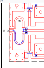
In many of the designs, I see a "coax through ferrite" 1:1 current balun, which I understand. However, in some designs, I am seeing another style of input balun shown in the picture below. I am trying to understand how this works, but I can't find what this type of balun is called, so I can't look it up to do the research on how it works / why it's used compared to the 1:1 current balun. To me, it looks like a TLT being terminated into two shorted microstrip transmission lines.
To me, this looks like a Marchand balun. I wanted to get a second opinion to check if I am correct in my assumptions. What I don't understand is why the additional shorted transmission lines are necessary.
Thank you
.png")
I have been tasked with designing a high power RF amplifier in the 100-500 MHz range. I work with RF, but have never designed an RF S.S. amplifier, so this is almost entirely new to me.
In many of the designs, I see a "coax through ferrite" 1:1 current balun, which I understand. However, in some designs, I am seeing another style of input balun shown in the picture below. I am trying to understand how this works, but I can't find what this type of balun is called, so I can't look it up to do the research on how it works / why it's used compared to the 1:1 current balun. To me, it looks like a TLT being terminated into two shorted microstrip transmission lines.
To me, this looks like a Marchand balun. I wanted to get a second opinion to check if I am correct in my assumptions. What I don't understand is why the additional shorted transmission lines are necessary.
Thank you