Continue to Site

Welcome to EDAboard.com

Welcome to our site! EDAboard.com is an international Electronics Discussion Forum focused on EDA software, circuits, schematics, books, theory, papers, asic, pld, 8051, DSP, Network, RF, Analog Design, PCB, Service Manuals... and a whole lot more! To participate you need to register. Registration is free. Click here to register now.

3-axial Accelerometer signal conditioning (ADC reading)

Status
Not open for further replies.

jadkh

Newbie level 4
Joined
Aug 24, 2021
Messages
6
Helped
0
Reputation
0
Reaction score
0
Trophy points
1
Activity points
90
Hello,
I found a 3-axial accelerometer with +/-500g that has a +/-1.25V range. The bias voltage (0g) is at half of the reference given (It does not give negative voltage).
If I'm supplying it with 3.3V, the bias voltage will be at 1.65V, so the range will be nominally 0.4V to 2.9V.
I am to read it with a 12-bit resolution ADC (ADS7038).
Can anyone help me with matching the readings of the ADC to obtain -500g at 0.4V and +500g at 2.9?
I appreciate your help.
 

Hi,

a rather expensive device...

Did you read ADC datasheet, especially section 8.3.3?
Using the datasheet informations you get:

ADC_reading = V_in * 2^12 / AVdd (the ADC reading is as usual in LSB)

(It´s rather basic and true for many basic ADCs...)

Klaus
 

Hello,

Thank you for your reply.
In fact, using the formula, if we have 3.3V as AVDD, 0.4V will yield to 496, and 2.9V to 3600.
How to have -500 and 500 as readings. Should I use a mapping function or something like that?

My application requires 12-bit resolution, and the natural response of my sensor is >10000. Having 3 axes I would need a minimum of 60KSPS sampling, and more to ensure that the signal is not aliased. Do you have in mind a device that's not this expensive?

Jad
 

Hi,

Your post really is confusing to me.

How to have -500 and 500 as readings. Should I use a mapping function or something like that?
..simple math? You should be able to do that.

at zero gain you get VDD/2 as ADC_input. With formula before you get 2048 LSB.
Just subtract it form the subsequent ADC readings and get -2048...0...+2047 as ADC range
or +/- 1551 LSB for +/- 500G
to get a range of +/-1 you just have to divide the value by 1551 (just normalizing the range)
and to get a range of +/-500 you just have to multiply with 500

so in total:
accel = (ADC_reading - 2048) / 1551 * 500

--> subtract, divide, multiply .... no rocket science

and the natural response of my sensor is >10000
What does that mean? Where do you get 10000 from?

Having 3 axes I would need a minimum of 60KSPS sampling,
??? What have 3 axis to do with sampling rate? Please clarify.

and more to ensure that the signal is not aliased.
What signal do you expect to be aliased?
Just use appropriate analog anti aliasing filter. The sensor even just has a frequency response up to 6000Hz (-2dB).

Klaus
--- Updated ---

Do you have in mind a device that's not this expensive?
What I´d do: check distributor´s internet sites. Hint: there are sensors with built in signal conditioning and ADC.

Klaus
 
  • Like
Reactions: jadkh

    jadkh

    Points: 2
    Helpful Answer Positive Rating
Heyy, I am sorry for the lack of clarification.
Hi,

Your post really is confusing to me.


..simple math? You should be able to do that.

at zero gain you get VDD/2 as ADC_input. With formula before you get 2048 LSB.
Just subtract it form the subsequent ADC readings and get -2048...0...+2047 as ADC range
or +/- 1551 LSB for +/- 500G
to get a range of +/-1 you just have to divide the value by 1551 (just normalizing the range)
and to get a range of +/-500 you just have to multiply with 500

so in total:
accel = (ADC_reading - 2048) / 1551 * 500

--> subtract, divide, multiply .... no rocket science
For the math I got it, like you said it's not rocket science
What does that mean? Where do you get 10000 from?
So I should not look at the "natural response given by the datasheet, only at my frequency response (2-6000Hz).
??? What have 3 axis to do with sampling rate? Please clarify.
Do we agree that my ADC does not simultaneous sampling? So if I am sampling the 3 axes 1 by one, with 60KSPS ADC for example, I would be sampling each axis with 20KSPS. Please correct me if I'm wrong.
What signal do you expect to be aliased?
Just use appropriate analog anti aliasing filter. The sensor even just has a frequency response up to 6000Hz (-2dB).

Klaus
--- Updated ---


What I´d do: check distributor´s internet sites. Hint: there are sensors with built in signal conditioning and ADC.

Klaus
Oversampling does not remove the need to put a filter? And should I design it and build it myself or there are pre built filters?
 

Hi,
So I should not look at the "natural response
"Natural response" is no common expression. I guess it rather means "resonance frequency"

Do we agree that my ADC does not simultaneous sampling?
The Inputs are MUXed. No S/H in front of the MUX. A clear sign for "non simultaneous sampling".

You select a sensor according your requirements. (to meet your requirements, or better)
So .. before you select a sensor .. you should know your "frequency range of interest".
--> Please tell us.

According this you also choose the anti alias filter frequency.
You don´t choose anti alias filter by the sensor, because every "noise" with frequency above f_sample/2 will cause an alias frequency .. you can not filter away (unknown) alias frequencies on the digital side.

A the cutoff frequency of a filter is at -3dB which means the amplitude at this frequency is just attenuated to 71%.
And the according alias frequency amplitude is the same. So you choose cutoff frequency and sampling frequency in a awy that alias frequencyies are attenauted to a "tolerable" amplitude.
--> You have to define this.

Nyquist says the sampling frequency needs to be higher than 2 x frequency of interest. So 2 x is too low.

Oversampling does not remove the need to put a filter? And should I design it and build it myself or there are pre built filters?
The higher the ratio: (sampling_frequency / cutoff_frequency) the easier. But it does not automatically mean you can omit the filter.

Usually you design the filter yourself, because only you know your requirements.
We don´t know your requirements.

Klaus
 

    jadkh

    Points: 2
    Helpful Answer Positive Rating
You select a sensor according your requirements. (to meet your requirements, or better)
So .. before you select a sensor .. you should know your "frequency range of interest".
--> Please tell us.
I have a norm that I should follow (EN1177). The sensor's frequency range is minimum between 1 and 1000Hz.
According this you also choose the anti alias filter frequency.
You don´t choose anti alias filter by the sensor, because every "noise" with frequency above f_sample/2 will cause an alias frequency .. you can not filter away (unknown) alias frequencies on the digital side.

A the cutoff frequency of a filter is at -3dB which means the amplitude at this frequency is just attenuated to 71%.
And the according alias frequency amplitude is the same. So you choose cutoff frequency and sampling frequency in a awy that alias frequencyies are attenauted to a "tolerable" amplitude.
--> You have to define this.
Also in the norm, we need a sampling rate higher than 20KSPS per channel(Axis). They stated that we need an anti-aliasing filter with -30dB at the half of the sampling rate.
 

Hi,
The sensor's frequency range is minimum between 1 and 1000Hz.
The sensor´s frequency range or the complete measurement equippment´s frequency range?

Also in the norm, we need a sampling rate higher than 20KSPS per channel(Axis). They stated that we need an anti-aliasing filter with -30dB at the half of the sampling rate.
Yes, these are useful requirements / specifications.
Use an online filter calculator and use your values to get an appropriate filter design.

If you use 20kSmpls/s you get 10kHz and the -30dB.
-30dB is about a factor of 1/30.
10kHz with 1/30 = 300Hz (raw estimation for a 1´st order filter) --> doesn´t work
10kHz with (1/30)^(1/2) = 1.8kHz (2nd order) --> may work
10kHz with (1/30)^(1/3) = 3.16kHz (3nd order) --> works

--> with a 3rd order filter you are on the safe side.

***
I agree that a simultaneous sampling ADC is useful.
Also oversampling may be useful.
Maybe you find a delta sigma simultaneous sampling ADC...

Klaus
 

    jadkh

    Points: 2
    Solved my filtering problem and made me understand what do I need as filter in my project
For future projects you might consider a single chip approach, PSOC 5LP family.
Compiler and IDE (PSOC Creator) free. Eval board that should work is $ 10.

The schematic window you see is internal components routed to effect a 3 chan
system digitized by the 12 bit SAR. In PSOC language a component is an onchip
resource.

1629826972805.png


The S/H can operate as Track and hold or S/H. The SAR is running at 180KSPS to
effect your needed 60KSPS channel requirements. The SAR I think can run up to
1 MSPS if you want even better approx simultaneous sampling. The SAR is free
running, drives the LUT to go to next chan when fin with current channel.

The SAR operated as diff, PGA and its input Vref allow you to tailor the range
of conversion.

The status reg used to get address of active channel. An ISR is used at SAR end of
conversion to get value. I think this can all be done total HW using DMA, just did not
have time to examine that facet. This would elim the need for ISR, CPU intervention.

You can see from right hand window most of the chip resources are unused,
available for other work. ARM core. Catalog of internal components attached.
COM, LCD, DSP, PWM...........logic......


Regards, Dana.
--- Updated ---

I was asleep at the switch. The whole point of using S/H was to
achieve simul sampling. This accomplishes that.

This is approach I would use, although I think I would add a little
internal logic to handle the muxing and trigger of the SAR in HW.
I just got lazy.

Here SAR runs at 1MSPS and S/H's at 120 Khz. simul.

1629832872519.png

--- Updated ---

Again single chip.
--- Updated ---

Regards, Dana.
 

Attachments

  • Component List (2).pdf
    183 KB · Views: 86
Last edited:
Hello, thank you for these constructive replies, you're being very helpful.


KLAUS:
Hi,

The sensor´s frequency range or the complete measurement equippment´s frequency range?
The sensor's
10kHz with 1/30 = 300Hz (raw estimation for a 1´st order filter) --> doesn´t work
10kHz with (1/30)^(1/2) = 1.8kHz (2nd order) --> may work
10kHz with (1/30)^(1/3) = 3.16kHz (3nd order) --> works

--> with a 3rd order filter you are on the safe side.
Got it!! so a 3rd order Low pass filter. I can use Butterworth or other? Sorry I forgot the notion of the filters.
***
I agree that a simultaneous sampling ADC is useful.
Also oversampling may be useful.
Maybe you find a delta sigma simultaneous sampling ADC...

Klaus
For future work I'm looking forward buying a simultaneous sampling one. For the moment it's just a final report, there's a pause in the project and after that I will continue working on it.


DANA:
For future projects you might consider a single chip approach, PSOC 5LP family.
Compiler and IDE (PSOC Creator) free. Eval board that should work is $ 10.
That's like magic! I might consider it for the continuation of the project. What about wireless communication? Is there a compatible part for it, or a chip that has wireless embedded? or I will need to have a conventional wireless module?

I didn't look into the specs and all but I liked the design and your approach
This is approach I would use, although I think I would add a little
internal logic to handle the muxing and trigger of the SAR in HW.
I just got lazy.
What do you mean by that. Sorry for signal processing I'm a little bit a beginner. So I will dive deep into all this beginning next week


For all: the project is paused till next week. So when the work returns, I would like to describe in details my project, and ask you what do you think about it.

Thanks for all the help, and sorry for replying late.
 

DANA:
danadakk said:
For future projects you might consider a single chip approach, PSOC 5LP family.
Compiler and IDE (PSOC Creator) free. Eval board that should work is $ 10.
That's like magic! I might consider it for the continuation of the project. What about wireless communication? Is there a compatible part for it, or a chip that has wireless embedded? or I will need to have a conventional wireless module?

The PSOC 6 family dual core, used in many blue tooth applications. But it does not have
enough analog facilities to do the simul sampling. I would say stay with 5LP family and use

an ESP8266, $2 kind of part, to do a server and talk to the PSOC over SPI or I2C would be simplest.

I didn't look into the specs and all but I liked the design and your approach
danadakk said:
This is approach I would use, although I think I would add a little
internal logic to handle the muxing and trigger of the SAR in HW.
I just got lazy.
What do you mean by that. Sorry for signal processing I'm a little bit a beginner. So I will dive deep into all this beginning next week

Using internal LUT and logic fabric would have done the mux as a HW controlled versus SW controlled mux. And use the trigger input to SAR, derive that from SAR end of conversion and DMA transfer complete to move the sample values into memory. Think a HW controlled loop versus using ISRs and SW to get values and move them.


Regards, Dana.
 
Hi,

In my eyes itmakes not much sense to use a 1kHz bandwidth sensor to detect fast signals with a sample rate of 20kHz.
Even when you are interested in the peaks...a 10kHz sensor will show more realistic peak values. The 1kHz sensor will show reduced values.
And detecting peaks is not a simple task, because every filter will show a different step response.
The peak then depends on:
* the real peak signal
* the sensor response
* the filter (order, type)

If possible use some norm signals to validate the results of your measurement tool.

Klaus
 
Hello again electronics people!
Thanks for your replies that are helping me with my project.

I now received my sensor and ADC.
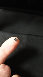
Their sizes really surprised me. The sensor can be soldered with QFN method without problem. I'm using KiCAD software to build the PCB.
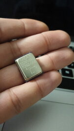
But when I received the ADC, I barely found it in the package. It is a <1mm chip with 17 pins. Without much experience with soldering, do you think I can do it with a little tutorial without breaking or damaging the ADC? or should I get help from a technician or company that do micro-soldering.
I attached the picture of the ADC/Sensor so you know what I'm talking about.

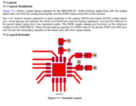
And about the KiCAD design of the ADC, could you tell me what are the dots at the 2 extremities of the capacitor(s)?
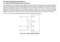
Which type of capacitor should I use? (Picture Attached) I read that I should use decoupling/bypass capacitor. I am using only analog inputs so should I short AVDD and DVDD?
Could you give me advice about the PCB, layers, or other things I should concentrate with designing the PCB since it's my first time.
Thank you
Regards

Jad
 

Attachments

  • Screenshot 2021-09-30 at 1.55.32 PM.png
    Screenshot 2021-09-30 at 1.55.32 PM.png
    276.4 KB · Views: 107
  • Screenshot 2021-09-30 at 3.21.46 PM.png
    Screenshot 2021-09-30 at 3.21.46 PM.png
    212.2 KB · Views: 120
  • IMG-20210928-WA0018.jpeg
    IMG-20210928-WA0018.jpeg
    1.3 MB · Views: 112
  • IMG-20210928-WA0016.jpeg
    IMG-20210928-WA0016.jpeg
    1.3 MB · Views: 112

But when I received the ADC, I barely found it in the package. It is a <1mm chip with 17 pins. Without much experience with soldering,
You say <1mm, but datasheet says 3 x 3 mm. I´m surprised, too.

Soldering: with an iron it´s about impossible to solder the center pad.
You have to use some reflow technique.
I recommend an experienced person should show you.
For any company that is used to SMD soldering it´s not a big deal.

Theoretically a kitchen stove or hot plate can do... but that comes with some risks.

*****
what are the dots at the 2 extremities
which dots? Schematic ? PCB?

***
Capacitors:
Standard decoupling capacitors are 100nF, X7R ceramics. 0603, but 0805 are more easy to solder.
But to use the correct ones you need to read the datasheet (I also have to do this for every device individually).

I am using only analog inputs so should I short AVDD and DVDD?
No. You surely use SCK, SDI, CS_n ... which are digital inputs.
Please follow the datasheet recommendations.

PCB:
Again. The datasheet is your friend.
Please also visit the manufacturer's internet page of the ADC and look for application notes, design notes, evaluation boards and their documentation (they often include PCB layout informations).

Klaus
 
Last edited:

You will learn a lot from your trial and errors. How not to test, solder, assemble, choose parts, design, and define expectations with assumptions listed. I listed these in reverse order because the last item must be the 1st and most important task done 1st. But before you can succeed in this even with all the excellent advice so far is to observe and reverse engineer how all of this is done by experts.

I gather from your ref to EN 1177 that this refers to the mechanical attenuation of impact of surfaces in kids playgrounds,

some random comments, FWIW

- a sensor with a linear range of +/-500 g seems excessive since freefall (-1g) is only 2.5mV ( you must use many tricks to get your noise level down below this level)
- fragility curves are interesting due to strength of materials and damage boundary curves of any mass with a given shear strength to fracture when you plot velocity vs accel. m/s. vs. g. plots change with mass and fragility of bones.
- even elastic materials like Solithane or "Lord mounts" designed to dampen the Q=gain at resonance = the natural frequency will have an acceleration gain of at least 5. There aren't many elastomers with a Q<5. So you want to avoid 10kHz which will ring like a bell. (Q>100) perhaps even consider a 3rd order LPF + Notch @ 10kHz

- you can estimate any g level by measuring the stopping depth from any height for a given mass.

i.e. drop height / stop height = accel [g] for any mass (assuming almost linear force response like playground foam or rubber chips or wood chips. )

I verified this rule of thumb of mine on testing fragility of hard disk drives from being dropped 1m in packing material as well as hard disk cartridges on hard counter tops used for OS updated in '80's

The test methods I used were analog using scopes. But the term "head crash" used for HDD's is just as significant to survivability as it is for children in playgrounds.

Dana's system approach is a good one to follow.
 
Last edited:

    jadkh

    Points: 2
    Helpful Answer Positive Rating
For future projects you might consider a single chip approach, uPSOC 5LP family.
Compiler and IDE (PSOC Creator) free. Eval board that should work is $ 10.

The schematic window you see is internal components routed to effect a 3 chan
system digitized by the 12 bit SAR. In PSOC language a component is an onchip
resource.

View attachment 171553

The S/H can operate as Track and hold or S/H. The SAR is running at 180KSPS to
effect your needed 60KSPS channel requirements. The SAR I think can run up to
1 MSPS if you want even better approx simultaneous sampling. The SAR is free
running, drives the LUT to go to next chan when fin with current channel.

The SAR operated as diff, PGA and its input Vref allow you to tailor the range
of conversion.

The status reg used to get address of active channel. An ISR is used at SAR end of
conversion to get value. I think this can all be done total HW using DMA, just did not
have time to examine that facet. This would elim the need for ISR, CPU intervention.

You can see from right hand window most of the chip resources are unused,
available for other work. ARM core. Catalog of internal components attached.
COM, LCD, DSP, PWM...........logic......


Regards, Dana.
--- Updated ---

I was asleep at the switch. The whole point of using S/H was to
achieve simul sampling. This accomplishes that.

This is approach I would use, although I think I would add a little
internal logic to handle the muxing and trigger of the SAR in HW.
I just got lazy.

Here SAR runs at 1MSPS and S/H's at 120 Khz. simul.

View attachment 171557
--- Updated ---

Again single chip.
--- Updated ---

Regards, Dana.

for -60 dB resolution and 1kHz BW does it matter if multiple(3) sensors are sampled synchronously? And muxed sequentially into a S/D converter within every 3us cycle per group.

Or sequentially sampled with 1 us conversion intervals per input or 3us per group of 3? I think not. The phase difference is 60 dB down at 1kHz.
 

Status
Not open for further replies.

Part and Inventory Search

Welcome to EDABoard.com

Sponsor

Back
Top