tony_lth
Advanced Member level 5
Hi, Gurus,
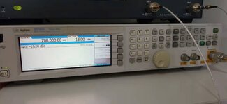
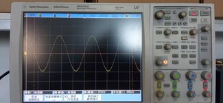
I met a strange result with oscilloscope to measure a -16dBm/700KHz sine wave signal.
The dispaly is 200mV Vpp.
But I calculated the Vpp should be 100mV.
What wrong with the measure?
Best,
Tony Liu
I met a strange result with oscilloscope to measure a -16dBm/700KHz sine wave signal.
The dispaly is 200mV Vpp.
But I calculated the Vpp should be 100mV.
What wrong with the measure?
Best,
Tony Liu