Continue to Site

Welcome to EDAboard.com

Welcome to our site! EDAboard.com is an international Electronics Discussion Forum focused on EDA software, circuits, schematics, books, theory, papers, asic, pld, 8051, DSP, Network, RF, Analog Design, PCB, Service Manuals... and a whole lot more! To participate you need to register. Registration is free. Click here to register now.

Symetrical AC input filter reduces common mode emissions?

Status
Not open for further replies.

cupoftea

Advanced Member level 5
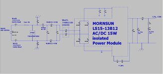
Joined
Jun 13, 2021
Messages
2,643
Helped
54
Reputation
108
Reaction score
116
Trophy points
63
Activity points
13,882
Hi
Is it really going to significantly improve Common mode emissions of an Offline 20W Flyback if i make the input AC filter symetrical?
At the moment i have Fuse-MOV-X2 capacitor-L(Diff mode)-Common mode choke-Diode bridge.
If i split the L(diff mode) into two and make the filter symetrical, will it really improve things?
 
Last edited:
Can't say without seeing a schematic with component values.
 
Thanks, the attached is it....its using the two 47uH's, instead of a single 100uH.

But i wonder if its also worth splitting the 12R inrush resistor into two equal ones and putting them in live and neutral.?...to give ultimate symettry?
 

Attachments

  • Symetrical mains filter_.jpg
    Symetrical mains filter_.jpg
    117.5 KB · Views: 164
The thing with asymmetric/unbalanced filters is that they can cause signal of one mode entering one port to be transformed into the opposite mode at the other port.

Let's assume the CM choke is perfect, and blocks all CM currents while passing DM currents. That doesn't mean you won't see any CM emissions on the mains. If the rest of the filter is unbalanced, then some of the DM emissions may show up as CM on the mains side.

As to what the exact effect will be, best way to find out is to simulate it, or better yet measure it experimentally.
 
Splitting a single diff mode inductor into two inductors, and putting them in live and neutral is something I like to do because I believe it makes the filter symmetrical, and thence reduces the demon common mode noise…but its hard to find written docs that support this on the web.

Actually I like having the two 47uH’s as they are because they give both DM and CM filtering.

Also, I reckon it would be a good idea to split the 12R, 5W inrush resistor into two aswell, and put them symmetrically…because I reckon these wire wound resistors have a impedance of some 100’s of Ohms at 100MHz?
 

Thanks, the attached is it....its using the two 47uH's, instead of a single 100uH.

But i wonder if its also worth splitting the 12R inrush resistor into two equal ones and putting them in live and neutral.?...to give ultimate symettry?

I highly suspect that your filter is not going to work, you will surely need more inductance to address the Differential emissions as a starter. (probably mH's).

Balancing the filter will increase the SRF of the filter and allow more but smaller inductance to be used but not that small.

I wouldn't use the ferrite beads until you 'need' them, they will work better close to the source of the noise as opposed to just putting them in the power line.

The use of mH's in the filter will naturally impede inrush currents so you may be able to lose your resistors or at least reduce them. The higher inductance will also have a higher resistance also which will help. The higher inductance will improve your low frequency emissions and will give the capacitors something to work against

C7 & C6 May work better the other side of the CM choke in real life, keeping the emissions off the wires. Currently your AC coupling noise onto the wires.

C1 & C3 Should probably be replaced with a Safety Cap between Chassis and the secondary 0V
 
I highly suspect that your filter is not going to work, you will surely need more inductance to address the Differential emissions as a starter. (probably mH's).

Thanks, this is interesting, your comments are greatly appreciated…this filter is very similar to the one recommended by Morsun in their LS15-13B12 datasheet (below - page 4) to give EMC compliance. They use a 330uH diff mode inductor, though I used a total of 94uH. We used 94uH because, as the LTspice simulation shows, it (along with the other filter components) greatly reduces the diff mode currents. (the LTspice is as attached, and includes circuit parasitics).

Mornsun LS15-13B12 datasheet:

The use of mH's in the filter will naturally impede inrush currents so you may be able to lose your resistors or at least reduce them.
Thanks, that’s a good point…we thought about using significant inductive transient suppression, but we don’t have the room, and the space we have for that means our diff mode inductors are going to saturate when a transient occurs...because we only have room for small inductors. (big enough not to saturate on the normal "nominal" current though)
The Mornsun application schematic in the datasheet uses 12R inrush resistor and 330uH diff mode inductor.

C1 & C3 Should probably be replaced with a Safety Cap between Chassis and the secondary 0V
Thanks again…this is a very interesting point you make. As you know, its standard in offline SMPS for class II equipment to fit a Y cap across the transformer, as in C1 and C3. We were tempted to also fit some capacitance from secondary GND to chassis. However, as it now finally transpires, our chassis will now be plastic. Also, the Mornsun datasheet recommends using Y caps across the transformer as per page 4 etc.

C7 & C6 May work better the other side of the CM choke in real life, keeping the emissions off the wires. Currently your AC coupling noise onto the wires.
Thanks, yes, we wanted to put some Y caps there as well but there was no room.
We had space for two Y caps at the input, and so put them as near the mains connector as possible, so that we didn’t have to route earth (from the mains connector) very far to get to the Y cap terminals of C6 and C7. We were worried about radiated noise getting to earth and causing common mode emissions, so decided to opt not to route earth too far into the board, where it would be nearer to the noisy switching stage.

I wouldn't use the ferrite beads until you 'need' them, they will work better close to the source of the noise as opposed to just putting them in the power line.
Thanks, you’re right we wanted them near to the source of noise (switching FET), but as you know, we couldn’t put them on the Mornsun PCB. We then wanted the filter capacitors (C5 and C19) to be the closest thing to the Mornsun PCB. Then we decided that with our space constraints, we would put them at the mains connector…because at least in this place they would show some impedance to any noise which had jumped around the AC filter components.
 

Attachments

  • Flyback offline _12v 15w _DCM.zip
    2.4 KB · Views: 81
Last edited:

Thanks, this is interesting, your comments are greatly appreciated…this filter is very similar to the one recommended by Morsun in their LS15-13B12 datasheet (below - page 4) to give EMC compliance. They use a 330uH diff mode inductor, though I used a total of 94uH. We used 94uH because, as the LTspice simulation shows, it (along with the other filter components) greatly reduces the diff mode currents. (the LTspice is as attached, and includes circuit parasitics).
No problem, 330uH (311R@ 150khz) is signifcantly more than 100uH (88R at 150Khz) thats 3 & 1/2 times the attenuation assuming the same filter capacitors. Annoyingly they also don't specify the CM choke which depending on its leakage will provide some differential inductance also. You should add the LISN circuit to your schematic also as at the switching frequency the LISN will look like a Capacitor which will sit accross your MOV and as it will be lower impedance than the Cx - 220nF it will supply any of the switching current.

Circuit on Page 4

https://www.ti.com/lit/wp/slyy202/slyy202.pdf?ts=1626103766420&ref_url=https%3A%2F%2Fwww.google.com%2F

Mornsun LS15-13B12 datasheet:


Thanks, that’s a good point…we thought about using significant inductive transient suppression, but we don’t have the room, and the space we have for that means our diff mode inductors are going to saturate when a transient occurs...because we only have room for small inductors. (big enough not to saturate on the normal "nominal" current though)
The Mornsun application schematic in the datasheet uses 12R inrush resistor and 330uH diff mode inductor.
Fair enough, best you simulate it first. I'm always skeptical when people claim compliance but don't disclose a BOM and PCB layout, its a nice disclaimer.

Thanks again…this is a very interesting point you make. As you know, its standard in offline SMPS for class II equipment to fit a Y cap across the transformer, as in C1 and C3. We were tempted to also fit some capacitance from secondary GND to chassis. However, as it now finally transpires, our chassis will now be plastic. Also, the Mornsun datasheet recommends using Y caps across the transformer as per page 4 etc.

Its a RF short circuit so will help with conducted emissions. If you are using plastic housing then for sure it'll need screening or you could have radiated issues.


Thanks, yes, we wanted to put some Y caps there as well but there was no room.
We had space for two Y caps at the input, and so put them as near the mains connector as possible, so that we didn’t have to route earth (from the mains connector) very far to get to the Y cap terminals of C6 and C7. We were worried about radiated noise getting to earth and causing common mode emissions, so decided to opt not to route earth too far into the board, where it would be nearer to the noisy switching stage.
It more to do with the direction of the CM current flow, you may have to try it for real. If the Y caps go to the other side of the CM Choke the circulating currents will stay off the cables. Current will take the path of least impedance, a CM choke is high impedance to CM currents whilst the capacitors will be Low impedance alternative. It will need the box screened to use Y caps though.
Thanks, you’re right we wanted them near to the source of noise (switching FET), but as you know, we couldn’t put them on the Mornsun PCB. We then wanted the filter capacitors (C5 and C19) to be the closest thing to the Mornsun PCB. Then we decided that with our space constraints, we would put them at the mains connector…because at least in this place they would show some impedance to any noise which had jumped around the AC filter components.

For sure C5 & C19 support most of the switching currents so need to be closest to the module, In their current location (schematically not physically) You may want to experiment with C6 & C7 schematic location as stated above
 
Last edited:
330uH (311R@ 150khz) is signifcantly more than 100uH (88R at 150Khz) thats 3 & 1/2 times the attenuation assuming the same filter capacitors
Thanks yes, though as the simulation in post #7 shows, the 94uH does the job and pretty completely filters out the diff mode high frequency noise.

You should add the LISN circuit to your schematic also as at the switching frequency the LISN will look like a Capacitor which will sit accross your MOV and as it will be lower impedance than the Cx - 220nF it will supply any of the switching current.
Thanks, the simulation (above post) uses a voltage sourc ewith very low impedance so will look like a big capacitor.

If you are using plastic housing then for sure it'll need screening or you could have radiated issues.
Thanks thats a great point you make because, As you know, without metal screening of the entire circuit including all the cables, we dont stand a chance of passing radiated emissions.
--- Updated ---

It will need the box screened to use Y caps though.
Thanks, though I’m sure you agree that even a class II device is better filtered for common mode emissions if you take earth to the mains switcher PCB input and use Y caps to it from live and neutral.

Yes, and its amazing that you don’t ever see it written anywhere on the internet or in any book anywhere…..that an offline SMPS based product, especially if there are wires/cables exiting/entrancing the PCB,…….. will absolutely need to be in a metal enclosure otherwise it will never pass radiated emissions testing. (it might be a “lattice” metal enclosure, or even a carbon fibre enclosure)
--- Updated ---

..or indeed it may just have a total lining of thin metal foil
 
Last edited:

Thanks yes, though as the simulation in post #7 shows, the 94uH does the job and pretty completely filters out the diff mode high frequency noise.


Thanks, the simulation (above post) uses a voltage sourc ewith very low impedance so will look like a big capacitor.


Thanks thats a great point you make because, As you know, without metal screening of the entire circuit including all the cables, we dont stand a chance of passing radiated emissions.
--- Updated ---
If you meet the conducted emissions usually the cables won't radiate so therefore they probably won't need screening. The main areas that need screening are the bits with high dv/dt such as mosfets, diodes and Transformer which is typically around the SMPS

Thanks, though I’m sure you agree that even a class II device is better filtered for common mode emissions if you take earth to the mains switcher PCB input and use Y caps to it from live and neutral.

Yes, and its amazing that you don’t ever see it written anywhere on the internet or in any book anywhere…..that an offline SMPS based product, especially if there are wires/cables exiting/entrancing the PCB,…….. will absolutely need to be in a metal enclosure otherwise it will never pass radiated emissions testing. (it might be a “lattice” metal enclosure, or even a carbon fibre enclosure)
--- Updated ---

..or indeed it may just have a total lining of thin metal foil
 
Status
Not open for further replies.

Similar threads

Part and Inventory Search

Welcome to EDABoard.com

Sponsor

Back
Top