dj_holmzy
Junior Member level 2
Hi,
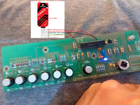
I have a faulty chip that I cannot read and am trying to programme a new one for replacement. The chip is pic16f870 and it came from an amplifier. I have gone through great difficulty just to get the device to read the chip in MPLAB IDE.
I have attached the schematic of the circuit with the chip I need to programme. Any help would be greatly apprectaited as currently the amplifier does nothing as the chip is dead. Believe to be electrostatically shocked in circuit. Thank you
")