Continue to Site

Welcome to EDAboard.com

Welcome to our site! EDAboard.com is an international Electronics Discussion Forum focused on EDA software, circuits, schematics, books, theory, papers, asic, pld, 8051, DSP, Network, RF, Analog Design, PCB, Service Manuals... and a whole lot more! To participate you need to register. Registration is free. Click here to register now.

Analogue audio frequency counter fix spread

Status
Not open for further replies.

neazoi

Advanced Member level 6
Joined
Jan 5, 2008
Messages
4,122
Helped
13
Reputation
26
Reaction score
15
Trophy points
1,318
Location
Greece
Activity points
36,951
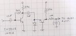
Hi I have found this frequency counter circuit which worked ok but I have a problem.

The range I am interested is 480Hz-2.7KHz only. Can I transform the circuit somehow to cover only this range, so that the meter spreads throughout it's whole scale instead of part of it, so as to increase the resolution of the meter?

Also I have no idea how the meter works, perhaps if I knew I could derive the modifications myself.

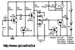
Any other such analogue meters with discrete components? I cannot find any on the net. Maybe you remember one from old magazines?
 

Attachments

  • 0-200kHz_Analog_Frequency_Meter.gif
    0-200kHz_Analog_Frequency_Meter.gif
    16.2 KB · Views: 89
Last edited:

Its a pulse counting detector. The input signal is first squared up then when the collector of TR2 is high, it charges the selected capacitor with ground being returned by the BE junction of D2. When the collector of TR2 goes low, the selected capacitor discharges through the BE junction of T3 and turns it on. It will work marginally better if you replace D2 with a Schottky signal diode so the capacitor charges to a slightly higher voltage. I'm not sure why the designer used transistors for D1 and D2, perhaps they had lots of spare 2N706s.

The range of measurement is never going to be very wide with this kind of circuit, you might be able to find a suitable capacitor value that covers the range you want but experimentation would be needed.

Brian.
 

    neazoi

    Points: 2
    Helpful Answer Positive Rating
Its a pulse counting detector. The input signal is first squared up then when the collector of TR2 is high, it charges the selected capacitor with ground being returned by the BE junction of D2. When the collector of TR2 goes low, the selected capacitor discharges through the BE junction of T3 and turns it on. It will work marginally better if you replace D2 with a Schottky signal diode so the capacitor charges to a slightly higher voltage. I'm not sure why the designer used transistors for D1 and D2, perhaps they had lots of spare 2N706s.

The range of measurement is never going to be very wide with this kind of circuit, you might be able to find a suitable capacitor value that covers the range you want but experimentation would be needed.

Brian.

All right I see how it works now, thanks! So basically it is the same idea like this pulse counter detector in a better squarer circuit (measured that on the scope).
Have you ever seen other types of analogue meter audio frequency indicators?
--- Updated ---

All right I see how it works now, thanks! So basically it is the same idea like this pulse counter detector in a better squarer circuit (measured that on the scope).
Have you ever seen other types of analogue meter audio frequency indicators?

That is needed is a audio frequency to voltage converter within the audio range 480Hz-2.7KHz actually. But isung discrete components. Any ideas are appreciated.
 

Attachments

  • fm detector.JPG
    fm detector.JPG
    20.5 KB · Views: 64
Last edited:

Simple frequency to voltage converter. High-pass filter followed by peak detector.
Capacitor values must be tailored to neighboring resistances.
By carefully adjusting all values you can create expanded scale for your meter readings.

freq-to-V converter high-pass then peak detect 270-2700 Hz.png
 

    neazoi

    Points: 2
    Helpful Answer Positive Rating
Simple frequency to voltage converter. High-pass filter followed by peak detector.
Capacitor values must be tailored to neighboring resistances.
By carefully adjusting all values you can create expanded scale for your meter readings.

View attachment 167668

Amazing, it worked!
And by adjusting the HPF I could achieve full range. And by adjusting the shunt resistor I could limit the maximum frequency. Thanks so much.

It strongly depends on the input signal level though. Any ideas how to cope with it in simple discrete electronics?
 
Last edited:

Last edited:

It strongly depends on the input signal level though. Any ideas how to cope with it in simple discrete electronics?
One idea is to clip the signal using two anti-parallel diodes. The result is square-ish waves of a uniform volt level. It produces the same rolloff curve, pretty much.

freq to V clipping diodes hi-pass then peak detec 270-2700 Hz.png
 

    neazoi

    Points: 2
    Helpful Answer Positive Rating
One idea is to clip the signal using two anti-parallel diodes. The result is square-ish waves of a uniform volt level. It produces the same rolloff curve, pretty much.

View attachment 167671
I like this simple idea better. Also active clippers can be used just like the pulse counter detector clipping stages. But the passive diode idea does not depend on any VCC it only depends on the diode characteristics.

Your HPF/peak-detector solution works very well, but I am not sure why a HPF is needed, what is it's function on the circuit? Because I have found it to affect the maximum range too. In fact more than the trimming of the shunt resistor in the peak detector. I think it creates a current proportional to frequency, but I am not sure how it does this.

Why is this input 1K resistor needed, can't I just remove it of extra sensitivity, or just replace it with a capacitor for DC isolation?

I also see you changed some values in the capacitors, is there a reason for that because of the clipper, or just for the simulation?
 
Last edited:

Circuit a clever design for sure.

Circuit has a strong T dependence, but if a one off thats probably not
an issue.....

Circuit also needs user cal to get any kind of absolute accuracy.

And if step response is of any concern circuit also has that as issue, eg. one trades off
ripple V out vs latency.

As an aside this can be done as follows (single chip) -

Essentially input period is measured and converted to V with a few lines of code using onboard
DAc.

1) VDAC accuracy user controlled to 12 bits
2) VDAC Vref onboard is +/- .1%
3) Step latency ~one cycle of input period. If input is known duty cycle,
say 50%, then response cut to ~ 1/2 input period.
4) Clk accuracy onchip used to measure period as good as +/- 1% not using xtal,
using xtal << .1%.....
5) Input signal level irrelevant as long as it meets logic levels, or use onchip
comparator to handle a signal that does not meet logic levels.
6) Overrange and under range can, in code, simply be set as saturating, eg. fixed
0 V for under range, Vmax, for overan ge, as set by your limit.

1613912941420.png


Most other chip resources available for other tasks. See right hand window, resources used/left.


Regards, Dana.
 
Last edited:

    neazoi

    Points: 2
    Helpful Answer Positive Rating
I like this simple idea better. Also active clippers can be used just like the pulse counter detector clipping stages. But the passive diode idea does not depend on any VCC it only depends on the diode characteristics.

Your HPF/peak-detector solution works very well, but I am not sure why a HPF is needed, what is it's function on the circuit? Because I have found it to affect the maximum range too. In fact more than the trimming of the shunt resistor in the peak detector. I think it creates a current proportional to frequency, but I am not sure how it does this.

Why is this input 1K resistor needed, can't I just remove it of extra sensitivity, or just replace it with a capacitor for DC isolation?

I also see you changed some values in the capacitors, is there a reason for that because of the clipper, or just for the simulation?


I revise this idea.
You see two antiparallel diodes acting as a clipper, will square the signal applied to the detector. Won't this contain all short of harmonics, i.e interfering with the frequency measurement we are trying to do?
 

Post #7 is just a clipper and high pass filter. The reason it works is nothing more than the roll off of the filter making lower frequencies produce lower output than high ones but it has a serious flaw: the clipping limits the signal level to +/- Vf of the clipping diodes and the rectifier also loses Vf of that diode so the output will be very low and potentially could be zero. It will only work if the clipping diodes have higher Vf than the rectifier and the maximum voltage at the output will be the difference between the two.

It isn't anywhere near as efficient as the pulse counting circuit where the 'squaring' action of the pump transistor provides the voltage to charge and discharge the capacitor.

I still think a three or four component MCU solution would be FAR better.

Brian.
 

It isn't anywhere near as efficient as the pulse counting circuit where the 'squaring' action of the pump transistor provides the voltage to charge and discharge the capacitor.
Right thanks for the explanation Brian.

The ultimate thing would be to be able to achieve full deflection even with a much lower bandwidth than the 470-2700KHz, ray within 100Hz or so near the 1KHz. I wonder can I somehow expand the resolution (and reduce the range) in the pulse counter circuit in post #1 to achieve something like this?

For example the 0-200Hz range is fine but I want it to be shifted to higher frequencies, say 800-1000Hz.
 
Last edited:

Neazoi is trying to avoid using ICs so he is looking for a discrete component design. This would be so easy and accurate with an MCU, even if it was to drive an analog meter.

The trouble with pulse counting meters is the conflict between capacitor value giving frequency range or voltage range, it is difficult to get both without swapping values. If you want more range you have to drop the value and increase the gain of the meter driver, however, the lower the capacitor the more ripple you get in the meter current which tends to make it less accurate.

Think of the problem as like trying to use a tennis bat to keep a ball in the air. If the amount of swing you can give is limited (= the pump voltage), moving the bat slowly ( = the frequency) will give a low average ball height but beyond a certain speed the ball doesn't go any higher, you just swing the bat before the ball has landed on it again.

Brian.
 

    neazoi

    Points: 2
    Helpful Answer Positive Rating
I also see you changed some values in the capacitors, is there a reason for that because of the clipper, or just for the simulation?

The term that seems to apply here is 'charge bucket'. I guess mine is passive. The other schematics are powered and have something in common with tachometer projects I've seen.

The idea is that each incoming waveform is converted to a measured pulse, which adds a small amount of voltage on the bucket capacitor. The more frequent the pulses, the higher it charges.

If pulses are sparse, the cap discharges quickly and no meter reading results.

Its charge should not be allowed it to rise too high, or else we lose linear response. So its charge must be kept to a fraction of incoming voltage. With clipping diodes the operating range is quite small. Nevertheless it can make the needle move on a plain D'Arsonval meter.

Why is this input 1K resistor needed, can't I just remove it of extra sensitivity, or just replace it with a capacitor for DC isolation?

I added an input resistor to hold to a real-life scenario. Without it the source signal sends infinite current through the diodes!
Similarly your applied signal has a certain amount of input resistance (although it may be unknown or invisible). The capacitor values need to be adjusted accordingly.
 

Neazoi is trying to avoid using ICs so he is looking for a discrete component design. This would be so easy and accurate with an MCU, even if it was to drive an analog meter.

The trouble with pulse counting meters is the conflict between capacitor value giving frequency range or voltage range, it is difficult to get both without swapping values. If you want more range you have to drop the value and increase the gain of the meter driver, however, the lower the capacitor the more ripple you get in the meter current which tends to make it less accurate.

Think of the problem as like trying to use a tennis bat to keep a ball in the air. If the amount of swing you can give is limited (= the pump voltage), moving the bat slowly ( = the frequency) will give a low average ball height but beyond a certain speed the ball doesn't go any higher, you just swing the bat before the ball has landed on it again.

Brian.
I guess we have to go back to basics -

1- Absolute accuracy desired ?
2- Resolution desired ?
3- Linearity desired ?
4- Environmentals operating in ?
5- One off or a production design ?
6- What is the "meter" being driven, D'Arsonval or digital ?

Regards, Dana.
 

I guess we have to go back to basics -

1- Absolute accuracy desired ?
2- Resolution desired ?
3- Linearity desired ?
4- Environmentals operating in ?
5- One off or a production design ?
6- What is the "meter" being driven, D'Arsonval or digital ?

Regards, Dana.

1. Accuracy does not matter, as long as it does not drift very much. i.e. when set and the meter dial calibrated, to stay in calibration.

2. This is probably an issue. If the detector/meter has big resolution this means that I can monitor a small part of the audio spectrum only. This is in fact more desirable, as it is more AF spectrum efficient. So big resolution at a small range is in fact much preferred than low resolution in a larger range.

3. I do not care. the meter scale can be made linear by relevant spacing of the different audio frequency steps. I can make the steps spaced further apart if the detector cannot distinguish them well in a particular range. Obviously the 2 above has to be taken care of.

4. HF radio, but the transceiver will deal with filtering etc.

5. One off. Discrete electronics.

6. Analogue meter 100uA
 

Status
Not open for further replies.

Similar threads

Part and Inventory Search

Welcome to EDABoard.com

Sponsor

Back
Top