Continue to Site

Welcome to EDAboard.com

Welcome to our site! EDAboard.com is an international Electronics Discussion Forum focused on EDA software, circuits, schematics, books, theory, papers, asic, pld, 8051, DSP, Network, RF, Analog Design, PCB, Service Manuals... and a whole lot more! To participate you need to register. Registration is free. Click here to register now.

Simple RF to DC converter loaded?

Status
Not open for further replies.

neazoi

Advanced Member level 6
Joined
Jan 5, 2008
Messages
4,122
Helped
13
Reputation
26
Reaction score
15
Trophy points
1,318
Location
Greece
Activity points
36,951
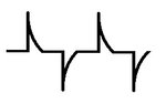
Hi I have a small "can" square wave oscillator at 3.5MHz and I want to rectify it's output with a series diode (1n914) and after that a shunt capacitor (100nF) to the ground.

When I measure with the multimeter I get a 1.2v DC out of the diode, when the RF out of the oscillator is 2.8vpp as measured in the 1M probe of the scope.

The problem is that when I connect a shunt resistor of even 10k parallel to the shunt capacitor, so as to load it, I get only 100mV or so.

I also tried to replace the 100nF with a 4.7uF ans I get only slighter voltage.

What am I doing wrong?
 

Hi,

2.8Vpp on a symmetric output means +1.4V and -1.4V referenced to GND.
So reduce it by the voltage dropof an (almost unloaded) diode, then 1.2V is maybe more than expectable.

You really need to give complete informations. How's the output stage? Is it AC coupled with a capacitor?
What happens when you load the output with a simple resistor?

Klaus
 

    neazoi

    Points: 2
    Helpful Answer Positive Rating
Hi,

2.8Vpp on a symmetric output means +1.4V and -1.4V referenced to GND.
So reduce it by the voltage dropof an (almost unloaded) diode, then 1.2V is maybe more than expectable.

You really need to give complete informations. How's the output stage? Is it AC coupled with a capacitor?
What happens when you load the output with a simple resistor?

Klaus

Ok 1.2v is expected unloaded thanks.

I thought if would be clear from the first post, but I am writing it down again. there is no output stage. The output from the can square oscillator goes directly to a 1n914 diode and the other end of the diode is connected to a 100nf shunt capacitor to the ground. At this connection point, I measure the 1.2v with the multimeter. If I connect a 10k, even a 100k from this connection point to the ground (i.i. parallel to the shunt capacitor) I get only 100mv or so at the multimeter.

Also, If I connect the 1M scope probe directly to the oscillator output I get a square wave when there is no 10k resistor parallel at the shunt capacitor. But when this 10k is present, the signal on the scope is more like the attached waveform with it's peaks approaching 1.2vpp
 

Attachments

  • tmp.jpg
    tmp.jpg
    5.6 KB · Views: 58

Hi,

The waveform looks like there is a series capacitor.
If this case then a series diode will try to draw a DC current .. which is not possible with a series resistor.
Then the voltage at the capacitor will move in the direction (negative) that no current will flow through the diode...even if there is a pulsing input.

Klaus
 

    neazoi

    Points: 2
    Helpful Answer Positive Rating
What is part number of oscillator ? Is that getting loaded and dropping
its output V ?

Also consider using a small signal schottky diode or germanium diode versus
silicon diode to reduce diode drop.

If osc does not like much loading could always buffer it with OpAmp or emitter follower (NPN)
or source (jfet) follower.


Regards, Dana.
 
Last edited:

    neazoi

    Points: 2
    Helpful Answer Positive Rating
Hi,

The waveform looks like there is a series capacitor.
If this case then a series diode will try to draw a DC current .. which is not possible with a series resistor.
Then the voltage at the capacitor will move in the direction (negative) that no current will flow through the diode...even if there is a pulsing input.

Klaus
Yes, there is a series capacitor inside the oscillator (I opened it).

Can you explain me a bit what you said, I do not think I understand it.
There is the square oscillator, coupled with it's capacitor to a series diode and at the other end of the diode, a shunt capacitor to the ground. The oscillator outputs a square wave.

I expect the single series diode to rectify the Positive part of the square wave and charge the capacitor with these. What am I thinking wrong here?
--- Updated ---

Yes, there is a series capacitor inside the oscillator (I opened it).

Can you explain me a bit what you said, I do not think I understand it.
There is the square oscillator, coupled with it's capacitor to a series diode and at the other end of the diode, a shunt capacitor to the ground. The oscillator outputs a square wave.

I expect the single series diode to rectify the Positive part of the square wave and charge the capacitor with these. What am I thinking wrong here?

I just measured the square waveform and it goes from about -1,3v to +1.3v. Could this be the problem?
Should I look for an oscillator with a positive waveform referenced to the ground (eg. 0 to 5v) to solve the problem?
 

Yes, there is a series capacitor inside the oscillator (I opened it).

Can you explain me a bit what you said, I do not think I understand it.
There is the square oscillator, coupled with it's capacitor to a series diode and at the other end of the diode, a shunt capacitor to the ground. The oscillator outputs a square wave.

I expect the single series diode to rectify the Positive part of the square wave and charge the capacitor with these. What am I thinking wrong here?
--- Updated ---


I just measured the square waveform and it goes from about -1,3v to +1.3v. Could this be the problem?
Should I look for an oscillator with a positive waveform referenced to the ground (eg. 0 to 5v) to solve the problem?

Yes a TTL or CMOS oscillator, in general, will give you more drive.....pay attention to its C load
specs though.


Regards, Dana.
 

    neazoi

    Points: 2
    Helpful Answer Positive Rating
Yes a TTL or CMOS oscillator, in general, will give you more drive.....pay attention to its C load
specs though.


Regards, Dana.
I have never seen such a differential oscillator can up to now. I always thought that they were ttl or else above ground.
 

I have never seen such a differential oscillator can up to now. I always thought that they were ttl or else above ground.

Yes single ended predominant. But historically in ECL and CML work was not uncommon to see them.


Regards, Dana.
 

Yes single ended predominant. But historically in ECL and CML work was not uncommon to see them.


Regards, Dana.
This does not make sense. I measured all my CAN oscillators and they are all differential i.e. their waveforms swing above and below 0v. I have also measured my ad9851 dds and it is also differential.

What am I loosing here?

Maybe I shall try a multivibrator oscillator?
 

If it doesn't have a negative supply the output can't go below zero if it is DC coupled.

Respectfully, when you are looking at these waveforms are you using a x10 probe on your oscilloscope? If you are, is it possible the probe compensation is 'over compensating' as it does produce the effect you are seeing.

Brian.

I am using a 10x probe. HP10441A. It has a trimmer inside. You mean it is not calibrated correctly?

Ok I will test it on a direct cable connection.
--- Updated ---

I am using a 10x probe. HP10441A. It has a trimmer inside. You mean it is not calibrated correctly?

Ok I will test it on a direct cable connection.
I just measured it on the other channel with a 1:1 probe and setting in the scope. It still shows negative portion of the waveform like in the first channel.
 

To check the probe compensation, connect to the calibrator output on the scope, make sure the ground clip is connected then set the probe to x10.
Adjust for a few cycles of square wave at about half the height of the screen. Then adjust the probe capacitor so the rising and falling edges of the waveform are square with no rounding or spiking. If you don't do this, the probe will not have a flat frequency response and it can manifest as phantom pulses.

Brian.
 

Status
Not open for further replies.

Similar threads

Part and Inventory Search

Welcome to EDABoard.com

Sponsor

Back
Top