Continue to Site

Welcome to EDAboard.com

Welcome to our site! EDAboard.com is an international Electronics Discussion Forum focused on EDA software, circuits, schematics, books, theory, papers, asic, pld, 8051, DSP, Network, RF, Analog Design, PCB, Service Manuals... and a whole lot more! To participate you need to register. Registration is free. Click here to register now.

Load transient calculation

Status
Not open for further replies.

santosh_475

Newbie level 4
Joined
Aug 10, 2019
Messages
7
Helped
0
Reputation
0
Reaction score
0
Trophy points
1
Activity points
93
Hi all
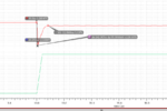
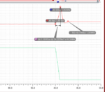
the load transient of the linear regulator when Iload varying from 0 to 10m with 1u rise time with an output capacitor of 200p, I want to know that how to calculate undershoot and overshoot voltage change? in my case delta vout = (Iload*risetime)/cout is not working.
it's very helpful if you provide any reference for a better understanding of load transient theoretical analysis like calculation of cout value from transient specification.

best regards
 

Attachments

  • tr1.PNG
    tr1.PNG
    29 KB · Views: 134
  • tr2.PNG
    tr2.PNG
    26.8 KB · Views: 91

Hi,

it´s a question of the feedbacked regulation loop within the regulator. (which you don´t show nor give any information about it)..
It´s not a simple problem of I_load, risetime, C_out

Klaus
 

At some point, every regulator's HF PSRR becomes a
function of the output filter and not the control loop.
This could be sub-100kHz for an old LM317, or over 1MHz
for some of the newer LDOs which offer improved HF
PSRR as a feature to make them useful as "cleanup"
for higher frequency switching power supplies.

In this case I recommend that first you assign the
risetime an application-realistic worst case; a 1uS
risetime on a large current step is not, usually. That
would prefer to have enough bulk filter to soak up
a lot of the current close-in, and give the control
loop the time it needs to catch up. What does the
load say to expect, or are you just making up test
challenges with characteristics the regulator just
can't be expected to meet?

You also need to consider that at Iload=0, the
control loop might be "wound up" trying to make
zero output current, and respond poorly to the load
step because it's not really closed loop linear. Might
instead do something like 1mA to 20mA, and see if
that behaves better.
 

1us risetime for a 10mA current step is usual I think, not in final applications maybe, but for testing it isn't surprisingly big. 1A/us slew rate is normal under validation. But I agree anyway.
I think check existing LDO datasheets for parameters and how they are tested, usually manufacturers share these in details.
 

Status
Not open for further replies.

Part and Inventory Search

Welcome to EDABoard.com

Sponsor

Back
Top