Continue to Site

Welcome to EDAboard.com

Welcome to our site! EDAboard.com is an international Electronics Discussion Forum focused on EDA software, circuits, schematics, books, theory, papers, asic, pld, 8051, DSP, Network, RF, Analog Design, PCB, Service Manuals... and a whole lot more! To participate you need to register. Registration is free. Click here to register now.

Simple discrete comparator for relatively low speeds.

Status
Not open for further replies.

neazoi

Advanced Member level 6
Joined
Jan 5, 2008
Messages
4,122
Helped
13
Reputation
26
Reaction score
15
Trophy points
1,318
Location
Greece
Activity points
36,951
Hi,
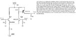
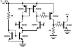
I would like to build a simple comparator out of discrete components.
The purpose is to compare a voltage of 0-5v on it's one input, to a voltage of 0-5v on it's other input and produce a zero or one at the output (0/5v).
I prefer an open collector output, with an emitter connected to the ground.
Single VCC of 5v.

Speed is not so important, it has to respond to less than 100Hz, so keep the circuit simple. The simplest the better.

Can you suggest me of any simple discrete circuits?


    neazoi

    Points: 2
    Helpful Answer Positive Rating

Build a simple diff pair, PNPs, powerd off ~ 9-12 Vdc, followed by a
single ended stages off the diff pair ....

Look at page 5 here -


But you give no specs, accuracy, input ofset, gain........


Regards, Dana.


Thanks! I like the first circuit, but I would like to see if there is a way to make it simpler by using less transistors?

I really have no specs, it will be used as on post #1 to switch on or off a LED. One input will be connected to the input DC (0-5v) and the other to a timing circuit (RC) to monitor the charge of a capacitor and compare it to that of the input DC signal.
Something like the attached schematic (man is so awful to have to upload an image every time I want to reference to a site!) but for dual inputs and single VCC
 

In first circuit you can replace Q1 and Q2 with R's, but you lose G.


Regards, Dana.
 

    neazoi

    Points: 2
    Helpful Answer Positive Rating
Can't I replace the Q5, Q6 with a single resistor to ground? 1K?
And Q7 and Q8 with a single npn with open collector?
 

Look at the schematic of the LM339. It's
the simplest comparator that might fit
your stated frame.

Now look at BOM cost of those transistors
and a couple of resistors as discretes
(just for one channel).

Then just buy the quad IC. Because size,
cost and reliability.
 

Can't I replace the Q5, Q6 with a single resistor to ground? 1K?
And Q7 and Q8 with a single npn with open collector?

No on single R for Q5 Q6, diff amp defeated.

No on single NPN verus Q7, Q8, you will not be able to shut off output.


Regards, Dana.
 

How about this simple one? But this has symetrical voltage, can I transform it into non-symetrical?
 

Attachments

  • comp.jpg
    comp.jpg
    95.4 KB · Views: 579

I also love to build discrete component circuits. As a technical challenge and to keep my brain properly lubricated.
My wife does crosswords and puzzles, I do discrete circuits.

My advice? Simulate your ideas first. In the simulation software of your choice. When you have a basic working circuit, breadboard it with real world components and then using a scope and DMM, probe your way around and tweak as necessary.
Repeat N+1 times until you are satisfied with the performance.
HINT: a triangle wave generator is very useful to troubleshoot a comparator circuit.
PRO HINT: the impedance of anything connected to the input will drastically change behavior. Keep this in mind during the simulation.

On the other hand, if all you want is a simple circuit for a larger project, heed the advice provided by other members and get yourself a LM393.
 
  • Like
Reactions: neazoi

    neazoi

    Points: 2
    Helpful Answer Positive Rating
I also love to build discrete component circuits. As a technical challenge and to keep my brain properly lubricated.
My wife does crosswords and puzzles, I do discrete circuits.

My advice? Simulate your ideas first. In the simulation software of your choice. When you have a basic working circuit, breadboard it with real world components and then using a scope and DMM, probe your way around and tweak as necessary.
Repeat N+1 times until you are satisfied with the performance.
HINT: a triangle wave generator is very useful to troubleshoot a comparator circuit.
PRO HINT: the impedance of anything connected to the input will drastically change behavior. Keep this in mind during the simulation.

Thanks a lot!
I think I am going to build this one posted in the first link and redrawn, but I am going to use 2n2222 and 2n2907, I hope it is ok.. How can it's behaviour change by impedance?, the levels?
 

Attachments

  • Comparator_schematic.jpg
    Comparator_schematic.jpg
    22.6 KB · Views: 513

Hi,

You might enjoy reading the first few pages of this pdf app note about a much-used comparator; basically, it's the same design as you intend to implement and the current source is nice.

Besides breadboarding it, if you simulate the design you posted at 0°, 25°, and 100°C, you will notice how it's an efficient circuit that is easy to get to work correctly and also how temperature-dependent the extremely rudimentary current source and sink are, how the currents provided to the differential pair collectors change dramatically - it may or not matter for your temperature range of operation.

2N2222 and 2N2907 are fine for that circuit.
 

Attachments

  • snoa654a.pdf
    1.5 MB · Views: 275

    neazoi

    Points: 2
    Helpful Answer Positive Rating
Thanks a lot!
I think I am going to build this one posted in the first link and redrawn, but I am going to use 2n2222 and 2n2907, I hope it is ok.. How can it's behaviour change by impedance?, the levels?
That will not range/operate to ground.....unless you use a - supply for ther ground portion
of circuit.

Otherwise use PNP inputs but + supply must be ~ 2 volts higher that 5V.

Regards, Dana.
 

That will not range/operate to ground.....unless you use a - supply for ther ground portion
of circuit.

Otherwise use PNP inputs but + supply must be ~ 2 volts higher that 5V.

Regards, Dana.
Ok the circuit worked at once. I have not refined it but it did work.
 

Ok it worked ok, but it started to compare from 0.5v and up to 3v max.
I wonder if this range can be uncreased somehow both at the lower end (biasing of the input bjt?) and at the higher end.
 

PNP followers at the input, in front of your NPN
diff pair, would get you closer to a working range
that includes ground (or negative rail). The LM339
uses a PNP diff pair witn PNP followers before it,
and can work at or slightly below ground as the
diff pair can saturate slightly without much impact.

Now, if you really want your lashup comparator to
be a -good- comparator (like near-ideal input
offset voltage), you might consider using matched-
pair or matched-quad transistors in IC style
packaging. You can get quad NPN, quad PNP or 2/2
in a variety of packaging including perfboard-friendly
DIP14.


Your grab bag discrete BJTs have no particular
matching, could be from different wafers or lots if
you don't specify and pay for tighter source attributes.
Your discrete devices also want to operate at higher
currents than small signal IC transistors (mA vs uA),
though you can choose not to care if it's all in fun.
Using smaller of these matched-quads could let you
dial down the power if you pick ones with a beta peak
at lower Ic.

Of course they do cost more, but they are a way to
explore the goodness of device matching, key to
analog design.
 
  • Like
Reactions: d123

    neazoi

    Points: 2
    Helpful Answer Positive Rating
Status
Not open for further replies.

Part and Inventory Search

Welcome to EDABoard.com

Sponsor

Back
Top