Continue to Site

Welcome to EDAboard.com

Welcome to our site! EDAboard.com is an international Electronics Discussion Forum focused on EDA software, circuits, schematics, books, theory, papers, asic, pld, 8051, DSP, Network, RF, Analog Design, PCB, Service Manuals... and a whole lot more! To participate you need to register. Registration is free. Click here to register now.

How to connect a battery to buck converter when ac voltage is less than required

Status
Not open for further replies.

Bindu boora

Junior Member level 1
Joined
Jul 31, 2020
Messages
15
Helped
0
Reputation
0
Reaction score
0
Trophy points
1
Activity points
132
Hi everyone
Hope everyone is safe and sound


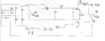
I am working on a project which consists of ac source,rectifier and buck converter and a voltage regulation circuit.The input varies from 110 to 120v and output is 5v..I have to design a circuit when the input voltage drops that is when it is less than 110 v .The circuit that is the buck converter circuit should be connected to a dc voltage of 28v and the rectifier circuit should be disconnected.Can I please know how to do it?.I attached the circuit also.Please take a look.
 

Attachments

  • Photo from Harshini.jpg
    Photo from Harshini.jpg
    141 KB · Views: 111

running the same buck converter from such different input voltages is problematic

i suggest you build another buck converter to take the 28 V to 5V
when the 110V is present, turn off the 28 V buck converter
when the 110 V is not present, turn on the 28 V buck converter

both 5V outputs can be diode couple to the output capacitor.
that is, one anode to 110 V converter, one anode to the 28 V converter,
both cathodes to the 5V output capacitor

perhaps one of the more experienced power converter gurus has a better idea
 
Install a relay to select which power source feeds the buck converter.

Arrange a control circuit to energize the relay's coil only when house voltage is sufficiently high.
 
Hi,

That's hard as the 110 to 120 V AC is a fluctuating source voltage. I'd maybe sample the rectified 110 VAC (and thus avoid the need for a dual supply or an additional circuit block to rectify or block the negative part of the 110V AC for the watchdog circuit - although even a simple reverse-biased diode at the lower resistor of the voltage divider for the V AC would keep input signals to a diode drop below ground) and feed it into a comparator via a voltage divider with a reference voltage on the non-inverting input with appropriate hysteresis for expected rectified ripple margin.

If the input to the comparator falls below Vref, its output should go low and in this way it can de-assert whatever controls that input source's pass device (MOSFET, relay, whatever...) and assert the 28V source's path. It's very simple logic: if A is high, B must be low, if A goes low B must go high. A simple NOT gate at the comparator output to complement and invert the comparator's output signal can be used for the Q OR !Q method of: If A = 1 then B = 0, if A = 0 then B = 1.

If you expect over-voltage peaks that might damage the control circuitry (the comparator and any logic devices), then you'd need to clamp the sampled input voltage with, for example, a precision clamp to somewhere between Vref and the comparator's supply voltage.

A large hold-up capacitor is needed at the junction of source A and source B where they meet the load, based on time it would take from A going low to B going high.
 

Hi,

You might want to look into power path management and load switches, etc. Might find a single-IC solution to control which supply should power the load based on UVLO (and OVLO onboard, etc.).
 
Status
Not open for further replies.

Similar threads

Part and Inventory Search

Welcome to EDABoard.com

Sponsor

Back
Top