Continue to Site

Welcome to EDAboard.com

Welcome to our site! EDAboard.com is an international Electronics Discussion Forum focused on EDA software, circuits, schematics, books, theory, papers, asic, pld, 8051, DSP, Network, RF, Analog Design, PCB, Service Manuals... and a whole lot more! To participate you need to register. Registration is free. Click here to register now.

Overheating of CGH40010F transistor in power amplifier testing

Status
Not open for further replies.

Mabrok

Full Member level 4
Joined
Mar 1, 2017
Messages
223
Helped
0
Reputation
0
Reaction score
1
Trophy points
18
Activity points
1,597
Hi,

I will use CGH40010F transistor in high power amplifier testing (upto 40 dBm output power). I have attached the transistor on heatsink directly without any interface (like indium foil or thermal paste) as this is my first time using this transistor and it is quite expensive, I am worrying about overheating and burn of the device during the power measurements? So, anyone have used this transistor please share your experience especially about overheating and input power limitations if any? Thanks in advanced.
 

If the heatsink has a sufficiently low thermal resistance and the surfance on which the transistor is in touch is not too rough I don't think you can have problems due to the overheating of the devices. In any case you should start from a lower output power and evaluate the temperature of the flange, to be sure not to exceed the junction temperature.
Be sure the Vgs negative voltage is present before to apply Vds otherwise the transistor will burn and when you swicth the bord off you have to switch first the Vds off and then the Vgs. In other words the Vgs must be always ON when the Vds is ON
 

    Mabrok

    Points: 2
    Helpful Answer Positive Rating
If the heatsink has a sufficiently low thermal resistance and the surfance on which the transistor is in touch is not too rough I don't think you can have problems due to the overheating of the devices. In any case you should start from a lower output power and evaluate the temperature of the flange, to be sure not to exceed the junction temperature.
Be sure the Vgs negative voltage is present before to apply Vds otherwise the transistor will burn and when you swicth the bord off you have to switch first the Vds off and then the Vgs. In other words the Vgs must be always ON when the Vds is ON
Thanks for your reply. How i can know that the heatsink has low thermal resistance? How to evaluate the temperature of the flang?
 

To estimate the thermal resistance you can use an online calculator. I don't know how reliable are them, but I suppose they could give an idea. For instance: https://www.heatsinkcalculator.com/
You could also estimate the thermal resistance simply measuring the temperture of the transistor by means of a thermocouple in contact with the flange (be sure to have a good contact between thermocouple and flange), since:

Tflange = Rheathsink*Dissipated_power + Tambient

The dissipated power is given by the DC power - RF output power.

To be sure you could also compare the Rheatsink from the measurement with that estimated by the calculator to see if they are in good agreement.

In order to estimate the junction temperature you will have to add the measured value with the product of the dissipated power by the junction-to-case thermal resistance (the value is on the data-sheet).

What kind of dissipator do you have in mind (I mean size and N. of fins) ?
 

    Mabrok

    Points: 2
    Helpful Answer Positive Rating
٢٠٢٠٠٩٠١_٠٩٥٥٤٨.jpg

I will use only this aluminium heatsink which its size 100×40×11 mm as heat dissipator
 

As far as my estimation is correct, your heatsink should have a thermal resistance of about 14 degC/W. Taking into account a junction to case thermal resistance of 8 degC/W we have 21 degC/W. Since the maximum junction temperature of the transistor is 225 degC, at an ambient temperature of 25 degC the maximum dissipable power is:

(225-25)/21 = 9.5W

This means that with 10W output power the efficiency must by higher of about 50%.
If you cannot use a more efficient heatsink, I suggest you tu use a small fan to cool the heatsink, in this way the thermal resistance of the heatsink greatly increases.
 

    Mabrok

    Points: 2
    Helpful Answer Positive Rating
As far as my estimation is correct, your heatsink should have a thermal resistance of about 14 degC/W. Taking into account a junction to case thermal resistance of 8 degC/W we have 21 degC/W. Since the maximum junction temperature of the transistor is 225 degC, at an ambient temperature of 25 degC the maximum dissipable power is:

(225-25)/21 = 9.5W

This means that with 10W output power the efficiency must by higher of about 50%.
If you cannot use a more efficient heatsink, I suggest you tu use a small fan to cool the heatsink, in this way the thermal resistance of the heatsink greatly increases.
How if i use laptop fan (external one that we use under the laptop)?. I put it under the heatsink
 

I think it should be OK.
 

If the Output Power 10W and the Amplifier is Class-A type, the Efficiency maybe 35% more or less so transistor must handle-at least-20W.
Design your heat-sink regarding to this value otherwise the transistor will go on its after life being as a room heater..;)
 

If the Output Power 10W and the Amplifier is Class-A type, the Efficiency maybe 35% more or less so transistor must handle-at least-20W.
Design your heat-sink regarding to this value otherwise the transistor will go on its after life being as a room heater..;)
The amplifier is class-AB, and according to the simulation should give efficiency of 60-70 %
 

You can't count on any particular thermal
impedance if you don't have paste or a
conformal interface pad. You might or might
not have full contact area depending on the
planarity and roughness of the two pieces,
and the method of attachment (like TO220
only dogs down one end and the other can
do what it pleases, with the "lever arm" of the
package on tab.

You could measure the close-in heat sink
baseplate temp and the transistor package
temp and then you'd know temp rise at the
interface.

Simulations of efficiency are worth very little.
They embed too many idealistic assumptions
especially regarding parasitic losses and
matching (which can greatly affect power
transistor dissipation, crest voltages and so
on).

It would be smart to start with backed-off
power (supply and signal) and work your
way into trouble, rather than the opposite.
 

    Mabrok

    Points: 2
    Helpful Answer Positive Rating
You can't count on any particular thermal
impedance if you don't have paste or a
conformal interface pad. You might or might
not have full contact area depending on the
planarity and roughness of the two pieces,
and the method of attachment (like TO220
only dogs down one end and the other can
do what it pleases, with the "lever arm" of the
package on tab.

You could measure the close-in heat sink
baseplate temp and the transistor package
temp and then you'd know temp rise at the
interface.

Simulations of efficiency are worth very little.
They embed too many idealistic assumptions
especially regarding parasitic losses and
matching (which can greatly affect power
transistor dissipation, crest voltages and so
on).

It would be smart to start with backed-off
power (supply and signal) and work your
way into trouble, rather than the opposite.
"It would be smart to start with backed-off
power (supply and signal) and work your
way into trouble, rather than the opposite" Do you mean start with low input power and increase smoothly until i get the desired output power?
 

No paste = no transitor. If there is no paste, then the heatsink does nothing.

Its up to the engineer to consider, how much over or under the calculated value he needs to put. Calculations and simulations are never the same as real life.
 

The paste improve the contact between the two surfaces (transistor and heatsink) filling the roughness.

However, if the finishing grade of the surface of the heatsink is reasonable I don't think you can have problem even without paste. The use of a fan greatly improve the poor thermal resistance of your heatsink.
In any case as I already suggested start from a low output power and see what happen, measuring the flange temperature by means of a thermocouple after roughly 30 minutes, then compare the value you measure with that expecetd, if it's OK increase the output power.
 

    Mabrok

    Points: 2
    Helpful Answer Positive Rating
The paste improve the contact between the two surfaces (transistor and heatsink) filling the roughness.

However, if the finishing grade of the surface of the heatsink is reasonable I don't think you can have problem even without paste. The use of a fan greatly improve the poor thermal resistance of your heatsink.
In any case as I already suggested start from a low output power and see what happen, measuring the flange temperature by means of a thermocouple after roughly 30 minutes, then compare the value you measure with that expecetd, if it's OK increase the output power.
So, thermocouple can be connected directly to the flang " drain and gate side" during measurements. For confirmation, can i connect it before i start the measurements, so that i can mointor the temperature in the case if any rise happen?
 

Yes, you have to place the thermocouple directly in contact with the metallic tab of the transistor (the source). I don't know what you mean with "drain and gate side". Be sure about the good contact between thermocouple and flange: this is very important (I often place the thermocouple under the head of one of the two screws, using a couple of washers, but you should be very careful not to tighten the screw to much in order not to destroy the thermocuple, but tighten enough to guarantee a good contact transistor-heatsink furthermore you will have an additional thermal interface that is washer-flange).
Then when you switch the power on, the temperature will start to rise following an exponential law (like the chage of a capacitor). after some tens of minutes the temperature will stop that means you reach the thermal equilibrium. using the temperature value the component reached, the DC power you supply (Pdc) and the delivered RF power (Prf) you can estimate the junction temperature as
Tj = Tmeasured + 8*(Pdc-Prf) where 8 is the junction to case thermal resistance given in the datasheet.
You must be sure that Tj < Tmax (that is 225 degC). Take margin with respect to this value since, for sure, the measurement will not be very accurate.
The thermal resistance of the heatsink (including the contact resistance) can be estimated as:

Rheatsink = (Tmeasured-Tambient)/(Pdc-Prf)

you can try with and without the fan (starting from low RF power). The worst case is without fan and with the heatsink placed on a desk with the fins on the bottom side.
Furthermore when the fan the thermal equilibrium (for both starting from RF off or increasing or decreasing the power) will be reached faster.
 

    Mabrok

    Points: 2
    Helpful Answer Positive Rating
Yes, you have to place the thermocouple directly in contact with the metallic tab of the transistor (the source). I don't know what you mean with "drain and gate side". Be sure about the good contact between thermocouple and flange: this is very important (I often place the thermocouple under the head of one of the two screws, using a couple of washers, but you should be very careful not to tighten the screw to much in order not to destroy the thermocuple, but tighten enough to guarantee a good contact transistor-heatsink furthermore you will have an additional thermal interface that is washer-flange).
Then when you switch the power on, the temperature will start to rise following an exponential law (like the chage of a capacitor). after some tens of minutes the temperature will stop that means you reach the thermal equilibrium. using the temperature value the component reached, the DC power you supply (Pdc) and the delivered RF power (Prf) you can estimate the junction temperature as
Tj = Tmeasured + 8*(Pdc-Prf) where 8 is the junction to case thermal resistance given in the datasheet.
You must be sure that Tj < Tmax (that is 225 degC). Take margin with respect to this value since, for sure, the measurement will not be very accurate.
The thermal resistance of the heatsink (including the contact resistance) can be estimated as:

Rheatsink = (Tmeasured-Tambient)/(Pdc-Prf)

you can try with and without the fan (starting from low RF power). The worst case is without fan and with the heatsink placed on a desk with the fins on the bottom side.
Furthermore when the fan the thermal equilibrium (for both starting from RF off or increasing or decreasing the power) will be reached faster.
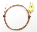
As there are many types of thermocouple, How about the attached one which is K-type? its temperature range -200 to 260°C. Can be used to mointor temperature? where i connect the wire side to one of the two transistor screws (without washer-flange, just under screw head) and the other side to the multi-meter, Am I right?
 

Attachments

  • Thermocouple.png
    Thermocouple.png
    1.1 MB · Views: 240

Since your transistor is expensive then a thermocouple could be easiest to work with to sense high temperatures in the expected range. As an alternate method there is the effect of heat on PN junctions. By squeezing a transistor between my fingers I make it warmer so it conducts slightly more. Current drops back down when I release it. It's not calibrated but it's easy and cheap.
 

As there are many types of thermocouple, How about the attached one which is K-type? its temperature range -200 to 260°C. Can be used to mointor temperature? where i connect the wire side to one of the two transistor screws (without washer-flange, just under screw head) and the other side to the multi-meter, Am I right?
The k-type thermocouple is OK and also its placement.
 

At Harbor Freight (not sure if this is accessible to you,
but take it as a pointer) they have fairly inexpensive
DMMs which include a Type K thermocouple in the
package. Centech 61593, I got for about $30 USD.
So you've got the readout too, along with a spare
decent quality handheld DMM (also happens to
have audio-range frequency and capacitance
functions and transistor hFE measurement).

Recommend attaching the thermocouple with
a dab of JB-weld or other high temp capable
epoxy, to ensure good thermal contact. Just
touching, is unreliable / unrepeatable.


As there are many types of thermocouple, How about the attached one which is K-type? its temperature range -200 to 260°C. Can be used to mointor temperature? where i connect the wire side to one of the two transistor screws (without washer-flange, just under screw head) and the other side to the multi-meter, Am I right?
 

Status
Not open for further replies.

Similar threads

Part and Inventory Search

Welcome to EDABoard.com

Sponsor

Back
Top