Continue to Site

Welcome to EDAboard.com

Welcome to our site! EDAboard.com is an international Electronics Discussion Forum focused on EDA software, circuits, schematics, books, theory, papers, asic, pld, 8051, DSP, Network, RF, Analog Design, PCB, Service Manuals... and a whole lot more! To participate you need to register. Registration is free. Click here to register now.

Fully differential amplifier with simple CMFB scheme on the differential pair

Status
Not open for further replies.

Junus2012

Advanced Member level 5
Joined
Jan 9, 2012
Messages
1,552
Helped
47
Reputation
98
Reaction score
53
Trophy points
1,328
Location
Italy
Activity points
15,235
Hello All

attached is a fully differential folded cascode amplifier with simple CMFB circuit on the input differential stage, the princible of this circuit is very easy and doesnt require sepearte amplifier or averaging scheme, however, I only see this type with booster ampliifer that used to increase the gain of the main ampliifer, I never seen it to be emplyed with the main ampliifer,

Could you please explain me why ?
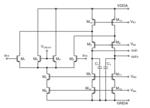
selfcmfb.PNG

Thank you in advance
 

Try to analyze circuit in three extreme cases:
1. Large input difference
2. Both inputs grounded (or for simplicity far below VCM, i.e. VCM-100mV)
3. Both inputs tied to supply (or simply 100mV above VCM)
 
Yes Dominik,

Thank you for your reply,

Indeed I just realized that VCM is compared to the input transistors (M1 & M2), but generally CMFB should the output common mode voltage gain, how it working for this circuit ?
 

Suppose you have a feedback of some sorts around this amplifier and you keep the input common-mode controlled. Suppose you don't have a signal. What will be the output common mode of the circuit?
 
Does it mean that this circuit is indirectly setting the common mode output voltages without sensing the outputs,

I dont know but whenever I look to the circuit to analyze it, I see that it is compring the input common mode voltage (vin1+Vin2)/2 with VCM,

For a general fullly differential amplifier at the DC operating point we should have Vo1 = Vo2 = VCM (assuming zero offset voltage), in this circuit the mechanisum is not clear for me
 

It is like in every amplifier. You can fix the output CM for example, which will fix the input CM. Here it is the opposite - fix the input CM and thus define the output CM. Here you sense the input CM through the diff pair. And the irtual short at the input summing junction is delivered by the feedback action around the amplifier.
However, I am not sure how good is this CMFB approach. Say, if you compare it with CMFB where you sense output CMV and feed back to correct it.
 
Dear Suta,

I think this CMFB can not be described as a genearl CMFB, complete operation of this circuit I guess should not be seperated from the main amplifier,, Otherwise according to your last statement, you are treating the common mode input as it is the same if it is the output common mode voltage in which the circuit work as follow

if input common mode voltage (vin1+vin2)/2 > VCMin, currents in M1 and M2 increase in comparing to the currents in M3 and M4, since the current in M13 and M14 are fixed (current source transistors), this lead to decrearse the currents in M5 and M6 thus it tries to rise the output voltage. Reverse mechanisim will happen if (vin1+vin2)/2 < VCMin.
 

Yes, exactly. So, by doing this through the outside feedback it will find a balance for the voltages.
 
Yes, exactly. So, by doing this through the outside feedback it will find a balance for the voltages.

Dear Suta,

Thank you for your help

Untill this point we are agree, but tell me please if the output common mode voltage (vo1+vo2)/2 is changing, who will detect it ?? and how it will by which mechanisim it will be corrected ?
 

I have not used this kind of CMFB but I think that if the output CMV changes that change will be reflected back to the input diff pair through the external feedback and will be compared with the reference CM voltage, after which it will correct for the currents at the output.
 
I have not used this kind of CMFB but I think that if the output CMV changes that change will be reflected back to the input diff pair through the external feedback and will be compared with the reference CM voltage, after which it will correct for the currents at the output.

That id why I was thinking that this circuit can not work as stand alone fully differential amplifier, and the control loop of this circuit only be true when it is part of the main amplifier, as I mentioned before this is used as a booster.
 

No high gain circuit can work as a stand alone amplifier. It always needs external feedback. This one here is no exception.
 
By looking only on common signal, the amplifier can be reduced to 3 branches. Diff-pair, with unloaded positive input transistor (its drain connected to supply) and negative input FET connected to current source and through the cascode to output. So this looks like single-ended opamp without current mirror branch.
The CM is provided to the output through more complicated source follower - feedback between diff outputs and inputs makes it for CM signal a simple non-inverting OPAMP with poor CMRR.

Thank you for your comment,

I will try to study what you explained before I reply to it,
 

Dear friends,

I have read couples of papers about this CMBF topology,

1. this type can only be used in closed loop configuration
2. it is mainly used for gain booster ampliifer, in which the amplifier already in loop with the cascoded transistors

Conclusion, based on the literature and your kind discussion, this technique is not so attractive as a stand alone CMFB , but its simplicity make it fast food for the gain booster amplifier

thanks
 

Status
Not open for further replies.

Part and Inventory Search

Welcome to EDABoard.com

Sponsor

Back
Top