Continue to Site

Welcome to EDAboard.com

Welcome to our site! EDAboard.com is an international Electronics Discussion Forum focused on EDA software, circuits, schematics, books, theory, papers, asic, pld, 8051, DSP, Network, RF, Analog Design, PCB, Service Manuals... and a whole lot more! To participate you need to register. Registration is free. Click here to register now.

Hunter fan electronic Id for a newbie

Status
Not open for further replies.

Thejdman01

Newbie level 6
Joined
Dec 18, 2017
Messages
11
Helped
0
Reputation
0
Reaction score
0
Trophy points
1
Activity points
82
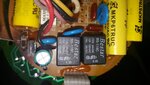
I have a large family room with 3 identical fans. One of the fans quit working. It has no pull strings only a remote. I really don't want to replace just one fan and keep the other 2 nor do I want to replace all 3. I have tried a few online sources and the manufacture and parts are no longer available for this fan. I took the fan receiver apart and think I found the problem, 2 pieces on the circuit board look brown and burnt. I would like to try replacing these 2 items and see if that fixes the problem, as I do know how to solder. I have tried 3 local computer stores, tv repair shops, etc trying to find out what these pieces are and get parts to fix the circuit board with no luck. There are no radio shacks or that kind of store in the area. If Someone would help identify the blown components so I could order what I need online and try to get this fixed i would greatly appreciate it. I'm not the.most tech savy person so if anyone could help identify the part what it is and size I would appreciate it.
 

Hi,

Add a close-up photo of the parts you are talking about and perhaps a photo of the whole circuit board using the insert image button. Maybe someone will be able to identify them, so long as they are not so burnt as to be unrecognisable.
 
90363.jpeg90364.jpeg90365.jpeg90366.jpeg
 

First picture is a 78L05 voltage regulator.
Second picture is probably a transistor but we need to see the side with the part number on it.
Other pictures are diodes. Again we need to know the number printed on them.

These all look like very inexpensive parts which should be easy to obtain but there are thousands of different types made in those plastic packages so we need the numbers to identify exactly which they are.

Brian.
 

I think he took a front side and back side picture of the voltage regulator Betwixt. Same with the diode I believe. Hard to figure out the complete numbers on the diode. Maybe the OP can post the numbers on the diode to see if there is any specific that he needs to know.
 

Yes the first 2 pictures are of one component, the second 2 pictures are of another (2nd) component, that as I said are pretty sure are the culprit of failure.
The numbers on the first component (in the first 2 pictues) are
78L05
A414
THE best I can tell.

THE numbers on the second 2 pictures (best I can make out) are
EIC49..
224D5

I sincerly appreciate everyone's help and input thank you.
 

Sorry for misunderstanding, I thought the pictures were of four different components.

The first is a 78L05 voltage regulator which is very common and available from most suppliers, it costs pennies.

The diode is less obvious to tell. That plastic shape is used for thousands of different types of diode so the number marked on it is essential. The 'E' is a styled logo from the manufacturer but I can't trace the '1C49' anywhere. Sometimes a product manufacturer has parts made with their own coding on them which makes it impossible to trace without a cross-reference list but I would think a fan manufacturer wouldn't use enough to make it worthwhile.

Can you post a picture of the whole circuit board, preferably both sides so we can get some idea of what it's function is and advise on a likely substitute.

Brian.
I asked the fan manufacture for a wiring schematic and they said they didn't have one. Here is the circuit board both sides, the part was in the empty slot labeled 17 where the board is extra brown (burnt brown). I appreciate it. 20171219_051049.jpg20171219_051210.jpg
20171219_051154.jpg20171219_051125.jpg
20171219_051102.jpg
 

I can see there is two PCBs. I assume that the top PCB for power supply and bottom PCB for controller. I can see a burnt zener diode Z1 (mostly the diode in the previous picture). Where is the location of the U1? Need more pictures.

- - - Updated - - -

I can see there are two PCBs. I assume that the top PCB for power supply and bottom PCB for controller. I can see a burnt zener diode Z1 (mostly the diode which is shown in the previous picture). Where is the location of the U1? Need more pictures.
 

The burnt spot labeled 17 that you speak of is actually Z1 I believe. Unless I'm overlooking it I don't see the 78l05 part. Is it maybe on another separate board. Also there is a component that looks to be mounted to the aluminum frame. It is just above the copper wound coil. Hard to tell from the picture but it looks like the top is blown out.

- - - Updated - - -

If the top is blown out of that part see if you can get some numbers off of it.
 
The burnt spot labeled 17 that you speak of is actually Z1 I believe. Unless I'm overlooking it I don't see the 78l05 part. Is it maybe on another separate board. Also there is a component that looks to be mounted to the aluminum frame. It is just above the copper wound coil. Hard to tell from the picture but it looks like the top is blown out.

- - - Updated - - -
Here is a picture of both boards the
If the top is blown out of that part see if you can get some numbers off of it.

Here is a picture of both boards. The board on the right in the lower left corner is where the 78l05 is. The left board in the lower right is where the diode was if this is a better picture and helps you figure it out. I took a picture or that copper wound coil if thst helps out. Thank you very much In advance.
20171219_161338.jpg
20171219_161550.jpg20171219_161400.jpg
 
Last edited by a moderator:

From this pictures, I can say that the power supply to the circuit got damages. The regulator exactly comes below the zener diode and I assume there is no high voltage isolation material to avoid the HV arc. The top PCB may have power supply and motor drive circuits. The power supply may be the main problem. If you can power it from an external 5V source, you can verify the condition of the remaining component.
I hope the remote is RF based one.
 
The board on the left is an RF remote control receiver and driver transistors for the relays on the right side board. This is one of those repairs that would take five minutes if it was on my workbench but could take a long time by remote diagnostic, especially as Thejdman01 does not have test facilities to hand.

The fault almost certainly lies in the right board (with the big yellow capacitors) and is almost certainly related to the power supply to the relays. I would guess Z1 and Q1 are a simple regulator to provide 24V for the relay coils. By implication, Z1 is probably a 25V (or close to it) Zener diode. My guess at the faulty part is Z1, Q1 or C4. All should be cheap and easy to replace so I wouldn't worry about which is the blame, spend $2 on changing all three.

We still need to identify the exact part number for that diode though. It might help if you could tell us the numbers printed on Q1.

Brian.

I agree 100 percent, parts seem fairly cheap and I would rather replace a part that doesn't need to be replaced necessarily then spend 1000 dollars replacing 3 fans. Like I said I tried every place local around a 50 mile radius I could and no one local would even look at it. The only test equipment I have would be a room.

THE numbers listed on the back of Q1 are
At the very top in 2 different circles are
11 02
In the middle it says
NEC
D882 0
And on the bottom it says
M 48


I appreciate all the help sincerly once again. Like I said anything that you would recommend replacing and trying I am more then happy to try as long as I know the name of the part and size.
 

Thanks.
It makes sense, the transistor is a 2SD882 made by Nippon Electric Company (NEC). It's nothing special, just a general purpose small power transistor so there are many suitable replacements. I'm not sure what is available in your region but if you can't find the exact type, the MJE182 and BD131 are drop in replacements.

Z1 is more of a problem as it appears to be a 'Zener' diode and although there are many alternative families, they all have members rated with different voltages and it's important the correct voltage is used as replacement. Unfortunately, the area on the copper side of the board underneath Z1 and Q1 is hidden under the wiring in your photographs so I'll have to ask you to take another one. What I need to see is the copper traces between Z1, Q1 and across to the relays (black square boxes) so I can see how they interconnect. From that I should be able to give you alternative numbers for Z1.

Brian.
 
Hello Thejdman01,
Prior to removing the zener diode or any other component, was there brown
glue touching or over the zener, especially around the component pigtails?
Since that area has seen a fair degree of heat over the years, there's a good
chance the glues properties have changed it enough to make it partially
conductive.
Please check the link regarding glue issues found on PCB's: HERE
Before replacing any parts, I would remove ALL signs of the glue. Even
ensure you clean it up on both PCB's.
It wouldn't hurt to measure all the grey colored 2 watt safety resistors to make
sure none have gone open circuit or high.
Regards,
Relayer
 

Thanks.
It makes sense, the transistor is a 2SD882 made by Nippon Electric Company (NEC). It's nothing special, just a general purpose small power transistor so there are many suitable replacements. I'm not sure what is available in your region but if you can't find the exact type, the MJE182 and BD131 are drop in replacements.

Z1 is more of a problem as it appears to be a 'Zener' diode and although there are many alternative families, they all have members rated with different voltages and it's important the correct voltage is used as replacement. Unfortunately, the area on the copper side of the board underneath Z1 and Q1 is hidden under the wiring in your photographs so I'll have to ask you to take another one. What I need to see is the copper traces between Z1, Q1 and across to the relays (black square boxes) so I can see how they interconnect. From that I should be able to give you alternative numbers for Z1.

Brian.
Thank you very very much I have attached a few pictures (some redundant) but hopefully gives you what you need to see. Thank you you have been very helpful.
20171220_185532.jpg
20171220_185518.jpg
20171220_185514.jpg20171220_185505.jpg20171220_185435.jpg
 

Attachments

  • 20171220_185430.jpg
    20171220_185430.jpg
    519.5 KB · Views: 182

Hello Thejdman01,
Prior to removing the zener diode or any other component, was there brown
glue touching or over the zener, especially around the component pigtails?
Since that area has seen a fair degree of heat over the years, there's a good
chance the glues properties have changed it enough to make it partially
conductive.
Please check the link regarding glue issues found on PCB's: HERE
Before replacing any parts, I would remove ALL signs of the glue. Even
ensure you clean it up on both PCB's.
It wouldn't hurt to measure all the grey colored 2 watt safety resistors to make
sure none have gone open circuit or high.
Regards,
Relayer

There was no clue around the diode however there is some other places I will be sure to clean up thank you
 

It's the other side of the board I need to see!

To work out an alternative to Z1 I need to see how it connect to the other components. The copper tracks on the other side of the board are like interconnecting wires between components so I need to be able to see both the component legs and how the copper tracks connect to them, in other words which solder joints are joined together. The component side pictures are fine, I can tell where the component legs are but without the underside photo I can't tell which connects to which.

I'm hoping the end of Z1 with band around it is connected to one of the outer pins of Q1 and the other outer pin goes to the relays, that would indicate it is a voltage regulator circuit to them. The top of the relay is marked "coil 24V" so that would be the voltage it has to produce. If I'm right, I can reverse engineer that part of the design to work out what Z1 is rated at and then suggest an alternative part number.

Brian.

Here are the pictures, the diode is in the upper right corner (where the 2 holes are where it was unsoldiered)20171221_160747.jpg
20171221_160826.jpg
 

Status
Not open for further replies.

Part and Inventory Search

Welcome to EDABoard.com

Sponsor

Back
Top