Continue to Site

Welcome to EDAboard.com

Welcome to our site! EDAboard.com is an international Electronics Discussion Forum focused on EDA software, circuits, schematics, books, theory, papers, asic, pld, 8051, DSP, Network, RF, Analog Design, PCB, Service Manuals... and a whole lot more! To participate you need to register. Registration is free. Click here to register now.

pullup resistor of microphone

Status
Not open for further replies.

jimkess

Member level 4
Joined
Dec 22, 2016
Messages
76
Helped
0
Reputation
0
Reaction score
0
Trophy points
6
Activity points
650
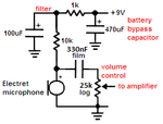
i am trying the following microphone circuit. In the diagram it says the resistor value depends on microphone. I tried, 10Ohm, 1Kohm, 10Kohm resistors but i get nothing at the output. However when i change the the POT, the value at the output changes which means that connection upto POT is good.

How can i determine the value of the resistor R1 in the circuit. I don't have the datasheet of the microphone but is very typical condenser electret.

Microphone-LM386-amplifier-circuit.png
 

R1 feeds power to a tiny fet transistor inside the microphone capsule that provides preamplification and impedance lowering. For 5V supply, its value can be around 1K-3K Ohm.

Test the microphone alone (with its supply resistor) in another proven-working amplifier.
 
Last edited:
Hi,

It depends on mircrophone type.
"Electret microphones" need this resistor, but not every microphone type needs it.

Klaus
 

When you look at datasheets of electret microphones then you will see that they use 0.5mA at about 2V or more.
Then with the 5V supply and 3V/0.5mA on the resistor, Ohm's Law calculates the resistor to be 6k ohms. Use 6.2k.
 

thanks, the 6.2Kohm as well as other 1k and 2k worked as I again tested. But I think 6.2KOhm was better in terms of sensitivity.
 

The resistor that powers the Jfet in an electret mic can feed power supply noise or even cause oscillations if a battery is used unless the resistor has an RC filter feeding it. I use 1K and 100uF from a 9V battery.
The gain of the Jfet is higher when the resistor powering it has a higher resistance. I have not tried using a high impedance current source which might cause the gain to be so high that the Jfet causes clipping.
There is a modification of an electret mic that changes the Jfet from the standard common source with gain to a source-follower with a gain of only 1 to allow a higher sound level without overload distortion.

can you provide an example of RC filter feeding the resistor? i connected speaker(8 ohm) at the output and heard pop sounds, is this noise due to power supply u were talking about? I had in mind to add a filter at the output(after 100uF or substitute it).

then could u also provide circuit or link to source follower type design?

happy to learn here,
thanks
 

Here is an example of the filter for powering an electret mic:
 

Attachments

  • power filter for an electret mic.png
    power filter for an electret mic.png
    6.8 KB · Views: 203
Here is an example of the filter for powering an electret mic:
great, thanks

not to brother you or annoy you more but how was the component value selected. as you know i have 5V supply.
 

I used a 1k resistor to feed the 10k resistor when the supply is 9V so with your 5V supply you can use the same ratio of 1/10th (620 ohms feeding your 6.2k ohms) and the filter capacitor can be 100uF or 220uF.
The 1/10th ratio reduces the voltage to the larger resistor value only 1/10th which is fine and the capacitor is calculated to cut frequencies above 1Hz or so.
 
Status
Not open for further replies.

Similar threads

Part and Inventory Search

Welcome to EDABoard.com

Sponsor

Back
Top