Continue to Site

Welcome to EDAboard.com

Welcome to our site! EDAboard.com is an international Electronics Discussion Forum focused on EDA software, circuits, schematics, books, theory, papers, asic, pld, 8051, DSP, Network, RF, Analog Design, PCB, Service Manuals... and a whole lot more! To participate you need to register. Registration is free. Click here to register now.

[SOLVED] Single byte read using 3 wire interface

Status
Not open for further replies.

tajiknomi

Member level 4
Joined
Nov 2, 2015
Messages
79
Helped
0
Reputation
0
Reaction score
0
Trophy points
6
Activity points
754
I am using 3 wire interface for communication with the RTC. The IDE i am using is MicroC Pro. And the simulation is done through proteus. Development language is C.

I am trying to communicate with DS1302 (RTC) using **broken link removed**MCU. In this project I'm also using LCD to display time/date etc and for that purpose i have wrote modules for LCD and they work just fine. Now i am trying to write methods for SPI,but before that, i just tried to read a single register (let say Hour-register) of DS1302 and put its value on a certain PORT/LCD so that i know how communication will take place b/w MCU and RTC. But i am doing something wrong because everytime i get the same value i.e. 0x01 when i read either date,hour,minutes or seconds etc.

Here is how i am doing to read the byte from RTC.
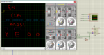
Code:
sbit EN at PORTC.B2;
sbit SCLK at PORTC.B3;
sbit SDI at PORTC.B4;
sbit SDO at PORTC.B5;

sbit EN_Direction at TRISC2_bit;
sbit SCLK_Direction at TRISC3_bit;
sbit SDI_Direction at TRISC4_bit;
sbit SDO_Direction at TRISC5_bit;

// SPI Initialization Fucntion

void SPI_init(void){

          INTCON |= 0xC0;     // GIE and PEIE enable
          SSPSTAT.SMP = 0;    // Sample at MIDDLE
          SSPSTAT.CKE = 1;    // Data send on Rising Edge
          SSPCON |= 0x21;    // Serial Port Enable, Idle state Clk is Low, F/16 => 31 KiloBytes/sec
          SCLK_Direction=0;
          SDO_Direction =0;
          EN_Direction  =0;      // Output Ports
          SDI_Direction =1;
          EN  =   1;                
}

// ============== Main function =============

void main(){

           SPI_init();
           EN=0;                       // Active low signal
           SSPBUF = 0x85;         // Hour Address
           while(SSPSTAT.BF == 0);     // Adress Transmission not complete ? Stay here
           value=SSPBUF;               // Read to Clear BufferFullStatusBit
           while(SSPSTAT.BF == 0);     // Recieve byte not complete ? Stay here
           value=SSPBUF;               // Store the recieved Byte
           EN=1;                       // Fininsh Reading
           PORTB=value;                // Transfer byte to PORTB
}

Here is setup
Capture.PNG

Here is the timing diagram for Read/Write of RTC
Capture.PNG

I don't want to use built-in libraries.

Any help would be appreciated.
 
Last edited:

Hi,

you set EN=0 at the beginning of transmission, but timing chart shows EN=1.


Klaus
 

hello,

bit WP must be RAZ

Code:
void write_ds1302(unsigned char B, unsigned char D){
 
     CS=1;
     write_Cde(B);
     SCLK=0;
     write_Donnee(D);
     CS=0;
 }
 
 unsigned char read_ds1302(unsigned char B){
     int i;
     unsigned char D;
     CS=1;
     write_Cde(B);
     TrisIO=1;
     D=0;
     for(i=0;i<7;i++)  
     {
     
     SCLK=1;
     Tempor(2);
     SCLK=0;
     Tempor(2);
    if(IO_R==1){ D= D + 0x80;}   
     D=D>>1;
     }
     CS=0;
     return(D);
 }
 
unsigned char  ds1302_init(void){
     unsigned char j;
     CS=0;
     Nop();
     SCLK=0;
     Tempor(10);
     write_ds1302(0x8E,0); // bit WP=0
     Tempor(10);
     write_ds1302(0x90,0x00);  // Trickle register disabled
     j=read_ds1302(0x81);// read second
     if((j & 0x80)!=0){
         write_ds1302(0x80,0);
     }    
 return(j);
 }
 

@KlausST Thanks for the reply, Here is the reason why I set EN=0 at the START, In PIC model it is shown as active-low pin. But they had named it RST, But if this is a reset pin, then where is EN pin ? In the datasheet , there is no RST pin !

Capture.PNG

@paulfjujo But I am only reading the register(in the above program) and WP is Write Protect Bit so it will be used BEFORE WRITING and here i am not writing anything.
 

hello,


so it will be used BEFORE WRITING and here i am not writing anything.

I think you must write somme valid data into all RTC registers , before using it
to get a correct RTC initalisation.
 

Hi,

EN = enable = high when running
/RST = low_active_Reset = LOW means reset = high means running
(in my eyes it complies)

But all discussion is unnecessary. --> Just do it like the datasheet says: SET it HIGH when you want to communicate.

Klaus
 
I have modified my program a little. here it is

Code:
// =================== Setting Control Register of RTC ================
           SCLK=0;                // Set CLK to low state before EN driven to High (RTC Datasheet)
           EN=0;
           Delay_ms(1);
           EN=1;
           SSPBUF = 0x8E;               // Control register ; select clock, Write operation
           while(!SPI_BUSY_FLAG);
           value=SSPBUF;               // Clear BF
           SSPBUF = 0x00;              // Clear WP bit
           while(!SPI_BUSY_FLAG);   // WP cleared ? if yes, move on
           value=SSPBUF;               // Clear BF flag
           EN=0;


// ====================== Read Hour Register =========================
           SCLK=0;                   // Set CLK to low state before EN driven to High (RTC Datasheet)
           Delay_ms(1);EN=1;
           SSPBUF = 0x85;               // Hour Register Address (write)
           while(!SPI_BUSY_FLAG);     // Adress Transmission not complete ?if yes, Stay here
           value=SSPBUF;                // Clear BF
           [U][B]while(!SPI_BUSY_FLAG);     // Recieve Hour byte not complete ? Stay here[/B][/U]
           value=SSPBUF;               // Store the recieved Byte*/
           EN=0;                       // Fininsh Reading
           PORTB=value;            // Transfer byte to PORTB*/

The program STUCK at the last while loop, I used that loop so that i can get the hour register data, but somehow BF doesn't get HIGH (i.e. recieve complete) so that i can exit from the loop.
Note: I'm not initializing the RTC as it will be automatically initialized to my system timing.

Capture.PNG
 

Proteus has SPI Debugger. You can see the transaction there.
 
I noticed from the above program that the SCLK was LOW ALL THE TIME (used an OSCILLOSCOPE) to find out (still doesn't know why it behave like that) though i have set the SCLK pin to output and configured it correctly (as far as i know).

Somehow i now wrote a discrete module for sending data to the slave. 1 Byte of data and adress is transmitted quite fine (shown by the osciloscope) but now when i used SPI Debugger to view the contents on the bus, it doesn't show up anything. Why ? Osciloscope shows the signals(data) quite fine but SPI Debugger doesn't !

SPI debugger Output

Capture.PNG

Osciloscope Output

Capture.PNG
 

Zip and post the mikroC project files and Proteus simulation file. I will check it.

In the DS1302 model of Proteus I see the pin name I/O and so both SDI and SDO are on the same pin.

After read command is sent you have to make the PIC MISO pin as input pin and then read the same I/O pin of DS1302.
 
Last edited:

I presume the SPI debugger expects active low SS signal, opposite to DS1302 operation.

The latest oscilloscope output looks wrong in so far that Enable is deasserted before the last clock cycle. Please compare with datasheet waveform.
 

Open the properties of SPI debugger and set the Idle state property of SCLK properly.
 

@okada: Kindly find the attachment herewith. I have already set the IDLE state in SPI Debugger according to my configuration i.e. SCLK idle state is low, still couldnt able to catch the bytes via SPI DEBUGGER.

@FvM: The previous snapshot was of the discrete module in which i manually changed the signal level. The orignal signal from the SPI is as follows. Here I am sending total 3 bytes viz. 0x8E to the control register followed by 0x00 to clear Write protect bit followed by 0x85 which is the hour register of RTC (which the MCU send successfully shown by the OSCILOSCOPE). In return I am expecting to get the hour value from the RTC but couldn't get it, either the RTC isn't replying OR i am not able to capture the byte.

Capture.PNG

Code:
           // =================== Setting Control Register of RTC ================
           SCLK=0;                // Set CLK to low state before EN driven to High (RTC Datasheet)
           EN=1;
           SSPBUF = [B]0x8E[/B];               // Control register ; select clock, Write operation
           while(!SPI_BUSY_FLAG);
           value=SSPBUF;               // Clear BF
           SSPBUF = [B]0x00[/B];              // Clear WP bit
           while(!SPI_BUSY_FLAG);
           value=SSPBUF;               // Clear BF flag
           EN=0;


// ====================== Read Hour Register =========================
           SCLK=0;                   // Set CLK to low state before EN driven to High (RTC Datasheet)
           EN=1;
           SSPBUF = [B]0x85[/B];               // Hour Register Address (read)
           while(!SPI_BUSY_FLAG);     // Adress Transmission not complete ? Stay here
           value=SSPBUF;              // Clear BF
           while(!SPI_BUSY_FLAG);     // Recieve Hour byte from RTC
           value=SSPBUF;               // Store the recieved Byte
           EN=0;                       // Fininsh Reading
           PORTB=value;          // Transfer byte to PORTB
}
 

Attachments

  • RTC.rar
    16.6 KB · Views: 84
  • Capture.PNG
    Capture.PNG
    119.9 KB · Views: 111

Looking at your DS1302 Proteus model I said that it has 1 pin for I/O and so 1 pin of MCU has to work as both MISO and NOSI. I will Check your files. I have to check the datasheet of DS1302 to answer correctly.
 

I have added a resistor for this scenario as shown below

Capture.PNG

But I think you are right, the above method would not work here (because the MOSI will also be read by MISO pin). I will try to use a single pin of the MCU for I/O but then i have to manually control the SCLK. I will give it a try.
 

Hi,

The circuit should work.
Usually it´s no problem that you read back (echo) your transmitting data.
This is only true as long as the slave´s IO is in HIGH-Z state.

Klaus
 

@KlausST: Yes, the circuit should work,

Here i have simplified my code. The module now sends the bytes successfully on each rising edge. And i can successfully read the seconds register value.
Now the problem I am facing is when i try to read the other registers i.e. MIN,HOUR,DATE,MONTH,YEAR etc, the RTC gives me values that are wrong but they have a pattern.
The values are always CONSTANT when i read the below registers except SEC register(which output the correct value). here is the pattern

Registers
Output

Sec
Correct value (compared to the clock)​
MIN
0xFF​
HOUR
0x00​
DATE
0xFF​
MONTH
0x00​
YEAR
0xFF​
Control register
0xFF
I don't know why only the seconds register is read correct and all others have the above mentioned pattern :|

Capture.PNG

Here are the two fucntions which i am using for reading and writing to the RTC

Code:
void SPI_SEND_DATA(char ADDRESS,char DATA){
           delay_us(1);
           EN=1;
           SSPBUF = ADDRESS;
           while(!SPI_BUSY_FLAG);
           value=SSPBUF;               // Clear BF
           SSPBUF = DATA;              // Clear WP bit
           while(!SPI_BUSY_FLAG);
           value=SSPBUF;               // Clear BF flag
           EN=0;
}

char SPI_RCV_DATA(char ADDRESS){
            delay_us(1);
            EN=1;
            SSPBUF = ADDRESS;
            while(!SPI_BUSY_FLAG);
            value=SSPBUF;               // Clear BF
            SSPBUF=0x00;                // Start the SCLK
            while(!SPI_BUSY_FLAG);      // Recieve data
            value=SSPBUF;               // Store the recieved Byte
            EN=0;                       // Fininsh Reading
            return value;
}

P.S : I couldn't modify the content of RTC because the CONTROL REGISTER (WP=1) gives me an output of 0xFF and the WP-bit isn't changing, i have tried sending 0x00, No luck!
 
Last edited:

Hi,

there are a lot of discussions in this forum about PIC code to cummunicate with DS1302.
Did you find a solution in these threads? (This is what a forum is for)

Why don´t you post your complete code?
As far as I can see your program snippets just show a single byte read....but your problem is with multi byte read...

Klaus
 

@KlausST:

I have viewed threads on DS1302 on this forum, none of them i could found which concern this issue. I am doing something wrong but i don't know where the problem lies.

Kindly find the full and compact code in the attachment along with the simulation file of proteus. I am viewing the values of sec, min, hrs,days etc on PORTB .

I can ONLY read the seconds register correctly.
 

Attachments

  • Upload.rar
    32.8 KB · Views: 86

Zip and post the complete mikroC PRO PIC project files.

Edit:

There is no main loop in code.

Code:
while(1) {

}

is missing.
 
Last edited:

Status
Not open for further replies.

Similar threads

Part and Inventory Search

Welcome to EDABoard.com

Sponsor

Back
Top