Warpspeed
Advanced Member level 5
- Joined
- May 23, 2015
- Messages
- 2,366
- Helped
- 773
- Reputation
- 1,548
- Reaction score
- 789
- Trophy points
- 1,393
- Location
- Melbourne, Australia
- Activity points
- 20,317
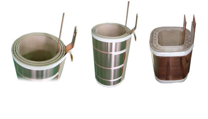
If you are trying to decide between using copper foil and litz wire for the primary, I would strongly recommend copper foil.
Litz is really good stuff, but it does have some disadvantages.
As you will know, it is a bundle of very fine wires which are individually insulated, and to strip, tin, and solder the ends can be quite difficult to do well.
Its also fairly bulky round wire, which can take up a lot of space because of air voids between turns.
Quite often a primary winding requires only a very few turns, and a lumpy litz winding can be difficult to wind another layer over the top of.
Copper foil obviously lays on very flat, and is much more space efficient, particularly where there are very few turns. Its really easy to place another winding over the top of foil. When you are experimenting and you need to maybe add a few extra turns, its easy to solder a few scrap lengths of foil end to end to increase the length.
You can buy copper foil on e-bay in fairly wide rolls that are easy to cut to the right width with scissors.
I have found foil much easier to work with than litz for heavy primary windings that have very few turns.
Its generally available in five thou and eight thou thickness’s, and you could wind on two or more foils on together to increase the thickness.
Three five thou foils is still very flexible. One fifteen though foil would be very stiff and quite difficult to work with.
If you are going to use a push pull topology, that will require two primary windings. Its quite important that they are wound on together, not one first, then the other on top. So start off with two foils, and two insulation layers, and wind the whole lot on together.
That will give much better coupling between the two primary halves, especially with foil.