Continue to Site

Welcome to EDAboard.com

Welcome to our site! EDAboard.com is an international Electronics Discussion Forum focused on EDA software, circuits, schematics, books, theory, papers, asic, pld, 8051, DSP, Network, RF, Analog Design, PCB, Service Manuals... and a whole lot more! To participate you need to register. Registration is free. Click here to register now.

Solar MPPT for panel voltage significantly greater than battery voltage.

Status
Not open for further replies.

mrinalmani

Advanced Member level 1
Joined
Oct 7, 2011
Messages
463
Helped
60
Reputation
121
Reaction score
58
Trophy points
1,318
Location
Delhi, India
Activity points
5,285
Hi
I am asked to design a solar MPPT for a 48V battery system.
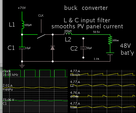
Open circuit voltage of a single solar panel is approx 36V. The user needs the MPPT to be compatible up 3 panels in series. This is approx. 100V open circuit voltage. Maximum power output should be near 70V in this case. But the battery voltage is only 48-50V. Boost converter based MPPT will probably not work.
Is it common to have panel arrangement where the battery voltage is lower than the maximum power point voltage of the solar panels?
Please give suggestions how to design a MPPT where the panel maximum power voltage is higher than the battery voltage.

Thanks
 

Hi,

when "input_voltage > battery_voltage", then no BOOST is used, but BUCK or STEP DOWN.

Klaus
 

Thanks for the reply...
But buck will probably need an input filter, and in boost I dont think it is necessary to use an input filter. If given a choice of voltage, what should be better? Buck or boost? Which is the most common topology used in the market? Any suggestions?
 

Maximum power output should be near 70V in this case. But the battery voltage is only 48-50V.

Then your aim is to take 70V panel output at, say 2A...
And chop it into pulses that charge a 48V battery.
A buck converter does this. The battery gets an average 2.9 A (or 2 x 70/48).

Top efficiency requires that you draw continual smooth current from the panels. To do this you need input filtering. An LC filter does this.
That way you get maximum utilization of the panels.


Notice the choppy waveforms going through the buck converter. However it draws constant smooth current from the PV panel.

- - - Updated - - -

I drew an output capacitor (C2), but not connected. It may be unnecessary when charging a battery.
 
Hi,

I drew an output capacitor (C2), but not connected. It may be unnecessary when charging a battery.
A battery is relatively high impedance for high frequency, causing a lot of voltage ripple.
Therefore I recommend to use a capacitor.

Klaus
 
In my MPPT system, I use the buck boost topology, it has the advantage that the input and output voltages are completely flexible, in fact they can cross over during normal operation.

Here is a sketch I drew for another thread, but it does show the basic topology.
It has the advantage of using an N channel mosfet with the gate directly driven by the PWM control chip.

buckboost.jpeg

The only peculiarity is that the solar panels have the positive side grounded to charge a 48v battery that has the negative side ground.

My own MPPT system is purely analog, and not shown on the above sketch.
 
You can use Buck Converter with N-Channel MOSFET. Or synchronous buck converter if you wish to operate it in high efficiency.
 

Attachments

  • mppt with synchronous buck converter.rar
    453.3 KB · Views: 149

Advantage of the inverting buck-boost topology is in using only one active switch and respective simple control.

I would opt for a four switch non-inverting buck-boost due to lower switching losses. Linear LT8705A supports up to 80V Vin/out.
 

Thanks for the reply...
It is clear that for high voltage, a buck converter with input filtering and low ESL MLCC capacitors at output will perform fine.
But there's a slight modification in the requirement.
The MPPT is required to operate from 50V to 120V. Power output is 1500W.
What should be a better choice, buck-boost converter or a dedicated buck and dedicated boost converter?
I am a bit hesitant about buck-boost converter delivering 1500W.
 

Regarding new specification.

Before designing the boost feature, I would check how much actual energy delivery can be expected at panel voltage below 56 V (or whatever your battery charge end voltage is supposed to be).
 

Power output is 1500W.

For this amount of power consider interleaving two or more converters. This splits the burden. (A single converter could have 50A peaks going through the inductor.)

Two interleaved converters draw a smoother current waveform from the panels. It reduces (or eliminates) the need for the LC input filter. And it reduces (or eliminates) the need for an output capacitor.
 
I am a bit hesitant about buck-boost converter delivering 1500W.
My own buck boost converter is designed for 200v to 300v input (8 x 24v 250 watt panels in series) and +230v dc output.
I actually have three of these 2Kw controllers in the one enclosure.

controller1.jpg

Efficiency is about 99% using a single 600v 48 amp mosfet.

The inductors are pretty large though, and the input filter capacitor is 2,200uF low esr type.

I prefer this topology because if it does blow up, the output always goes to zero in just about any likely failure mode.

If a buck converter mosfet shorts out it can do a lot of expensive over voltage damage to whatever is on the output side.
That thought terrifies me.
 
Thanks everyone for the reply.
I am deciding to settle down for an independent buck and independent boost converter that share the inductors.
Please refer to the attachment.
(Still scared of a buck-boost converter)
In my perception a buck-boost converter is more noisy than a buck or a boost converter. Please correct me if I am wrong.
Please also give comments on the topology shown in the attachment. (Ignore the values of components)
 

Attachments

  • Buck-Boost MPPT.PNG
    Buck-Boost MPPT.PNG
    10.3 KB · Views: 113

That should work, as long as it only needs to either buck or boost.
If the input and output voltages need to cross over during normal operation, that might present a problem.

Not sure what is going to happen controlling this around dawn and dusk as the input voltage goes to zero at night.
 

Status
Not open for further replies.

Part and Inventory Search

Welcome to EDABoard.com

Sponsor

Back
Top