kingtal0n
Junior Member level 3
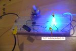
I'm trying my first 555 timer project. I was able to get a single LED to flash, however when I try to setup the two LED to go back and forth, the one "LO" Led always stays dimly lit. The instructions say this means the timer chip is bad, however I've tried about 10 different chips and they all do the same thing.
Another issue I noted is that the potentiometer does not seem to change the speed of the flashing. I've tried 2 different style of potentiometer also. I must be doing something wrong. I attached a picture without the LED lit so you can see my wires also.
I used a 10uf 250volt capacitor to "slow it down". I tried a smaller one and the led blinks faster like it should (just the one "hi" led only).
The resistors between the led are identical (220 ohm)
the resistor between 6 and 7 pin is 12k


I actually figured it out while I was typing this. I had the "lo" led wired wrong. Still, curious why the potentiometer isn't adjusting the speed of the blinking, although common sense is telling me I just need the right resistance there (the pot probably doesn't have the right range).
Curious now also, can I drive a transformer (such as from an alarm clock) with this square wave output safely to generate a secondary voltage A/C current? Or should I focus on forming a sine wave for that sort of thing. And I am also curious if I can use this square wave output to drive, say, a tachometer for a vehicle, or a idle control valve. I hope soon to program an arduino to control a solenoid in a vehicle... but that is a bit too much at this time.
Another issue I noted is that the potentiometer does not seem to change the speed of the flashing. I've tried 2 different style of potentiometer also. I must be doing something wrong. I attached a picture without the LED lit so you can see my wires also.
I used a 10uf 250volt capacitor to "slow it down". I tried a smaller one and the led blinks faster like it should (just the one "hi" led only).
The resistors between the led are identical (220 ohm)
the resistor between 6 and 7 pin is 12k


I actually figured it out while I was typing this. I had the "lo" led wired wrong. Still, curious why the potentiometer isn't adjusting the speed of the blinking, although common sense is telling me I just need the right resistance there (the pot probably doesn't have the right range).
Curious now also, can I drive a transformer (such as from an alarm clock) with this square wave output safely to generate a secondary voltage A/C current? Or should I focus on forming a sine wave for that sort of thing. And I am also curious if I can use this square wave output to drive, say, a tachometer for a vehicle, or a idle control valve. I hope soon to program an arduino to control a solenoid in a vehicle... but that is a bit too much at this time.