Continue to Site

Welcome to EDAboard.com

Welcome to our site! EDAboard.com is an international Electronics Discussion Forum focused on EDA software, circuits, schematics, books, theory, papers, asic, pld, 8051, DSP, Network, RF, Analog Design, PCB, Service Manuals... and a whole lot more! To participate you need to register. Registration is free. Click here to register now.

How Draw Modified Capacitance Loaded Loops(MCLL) in HFSS?

Status
Not open for further replies.

marif

Newbie level 1
Joined
Nov 5, 2016
Messages
1
Helped
0
Reputation
0
Reaction score
0
Trophy points
1
Activity points
7
Good Day!
I have to draw Modified Capacitance loaded Loops(MCLL) in HFSS.I am using version 13 of HFSS.I got struck in how I should draw the arc and assign it a certain angle for example 45 degree.Please help me solving the issue.I shall be thankful to you for the help.
 

Hello!

There are a number of ways to draw arcs in HFSS. I'll briefly introduce you to a few here to hopefully get you in the right direction.

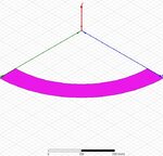
First, I'm going to assume that you're trying to draw something that looks like the image I've attached (image taken from an IEEE paper: Triple band-notched ultra-wideband antenna using a pair of novel symmetrical resonators).

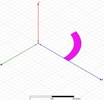
1) Draw an Equation Based Curve. (Draw > Equation Based Curve)

To draw an equation based curve, simply enter the parametric equations in Cartesian Coordinates (x(t), y(t), z(t)). The only thing to watch here is that you need to use the variable "_t" rather than just "t". Once you do this, you'll have an outline of your curve. You'll probably want to draw a second one that is slightly larger in order to give it some finite thickness. Once you have the two curves, you can connect them by selecting both curves then from the right-click menu select "Edit > Surface > Connect".
Eq_Based_Curve.jpg

2) Draw a center point arc. (Draw > Arc > Center Point).

A center point arc is a simple way to create a section of a circle. The center point arc tool requires four clicks:
1 - Click on the desired location for the center of the circle
2 - Click on the desired starting arc location
3 and 4 - Double click on the desired ending arc location

Similar to the first, you can draw a second one slightly larger than the first and then connect them using Edit > Surface > Connect.
Center_Pt_Arc.jpg

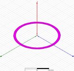
3) Use the Subtract operation. (Modeler > Boolean > Subtract).

Suppose you have two concentric cylinders, one with a slightly larger radius than the other. You may select the larger cylinder, then select the smaller cylinder, then use the boolean subtract operator. This will leave you with a cylindrical ring.
Subtract.jpg

I hope this is helpful!
 

Attachments

  • MCLL.JPG
    MCLL.JPG
    9.1 KB · Views: 99
Status
Not open for further replies.

Part and Inventory Search

Welcome to EDABoard.com

Sponsor

Back
Top