Continue to Site

Welcome to EDAboard.com

Welcome to our site! EDAboard.com is an international Electronics Discussion Forum focused on EDA software, circuits, schematics, books, theory, papers, asic, pld, 8051, DSP, Network, RF, Analog Design, PCB, Service Manuals... and a whole lot more! To participate you need to register. Registration is free. Click here to register now.

Circuit with current output of 100A dc

Status
Not open for further replies.

MH.AI.eAgLe

Newbie level 4
Joined
May 8, 2016
Messages
7
Helped
0
Reputation
0
Reaction score
0
Trophy points
1,281
Activity points
1,374
hello
I want to design a battery charger and in that design it is necessary that the current output reaches to 100A , i tried to find some circuits through the internet but i cant find useful circuit , so i wish some one would help me .
also here is a circuit with current output about of 30A , perhaps gives you some ideas . url1.jpeg
 

Continue to parallel the outputs until you get an output of 100+ amps. Also, find a better pass transistor than the TIP and don't expect to use a PCB to carry the current.
 
Thank you for answering
you are right, what type of pcb or something else would help me?
you mentioned about a kind of transistor , can you give me the part number?
thank
 

hello
I want to design a battery charger and in that design it is necessary that the current output reaches to 100A , i tried to find some circuits through the internet but i cant find useful circuit , so i wish some one would help me .
The easiest way to do this these days, is to get your hands on a 100 amp rated alternator from a vehicle graveyard, and drive it with a belt from a very large electric motor. The voltage regulator already within the alternator will solve most of the problems very simply.
 

Even if you have 100 Amps Available, Unless the Battery is Really LOW in Voltage and in Excellent Condition, it will never pull that 100 Amps.
 

You're right, I feel that I was wrong and it may be impossible.
thanks all
 

Its not impossible, just fairly difficult, and probably not extremely useful.

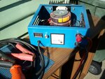
I built a high current 14v dc supply that can easily produce 100+ Amps for very short periods, and will start my small car instantly with even a dead flat battery.

But as Chemelec says, doing this will not charge the battery at 100 amps.
Within less than a minute the charging current drops back to perhaps 35 amps and continues to fall even lower.

Its good enough to start my car and prevent me from being late for work, and for that it has worked very well the very few times I have really needed it.

There are three 150 Va transformers with 11.8v secondaries which can safely produce about 45 amps continuous dc, but vastly more than that for very short periods.
This does require a three phase power which I fortunately have at home.
charger.jpg
 

Thank you for answering
you are right, what type of pcb or something else would help me?
you mentioned about a kind of transistor , can you give me the part number?
thank

im new here, but i seen some interesting DIY stuff
https://www.instructables.com/id/DIY-battery-tab-resistance-fine-spot-welder/
look at his cables, i think they are at least 10mm diameter to carry high current. some PCB design is normal, but they stack on top of the PCB track extra copper cable to carry current. but i think, your kind of charging will need 1 section that is all low current (the controls) and 1 section all high current (all copper wire/bar point to point).

the other way to look at this is design 10A charger, then make 10 of it, control by 1 MCU. if this is not possible due to parts, try even smaller current. but more sections = more painful to build, there is just so much parts ! there is just so much to consider to sync all separate chargers.
 

Status
Not open for further replies.

Similar threads

Part and Inventory Search

Welcome to EDABoard.com

Sponsor

Back
Top