Continue to Site

Welcome to EDAboard.com

Welcome to our site! EDAboard.com is an international Electronics Discussion Forum focused on EDA software, circuits, schematics, books, theory, papers, asic, pld, 8051, DSP, Network, RF, Analog Design, PCB, Service Manuals... and a whole lot more! To participate you need to register. Registration is free. Click here to register now.

What type of comparator should be used for dc-dc converters (buck, boost converters)

Status
Not open for further replies.

vieha007Electronic

Junior Member level 3
Joined
Feb 27, 2011
Messages
25
Helped
3
Reputation
6
Reaction score
1
Trophy points
1,283
Location
South Korea
Activity points
1,559
Hi all,

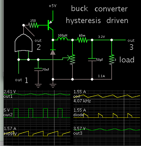
Can you tell me in the design of dc-dc converters (buck, boost), what type of comparator should be used?

And how about the specification for the comparator? I designed the hystersis comparator for buck converter with the switching frequency is around 1 MHz, however, when I simulate it in the time domain (with one terminal is fed by 10mV sine, and the other at dc), it delays too much.

(Please check the attached images below)

About the opamp, I can designed well with the specification, however, for comparator, I can't imagine clearly what is the spec of comparator, such as delay....

https://obrazki.elektroda.pl/9010683300_1476228003.png

<a title="Comparator2.png" href="http://obrazki.elektroda.pl/9010683300_1476228003.png"><img src="http://obrazki.elektroda.pl/9010683300_1476228003_thumb.jpg" alt="Comparator2.png" /></a>


Any replies from you are really appreciated!

Sincerely,
 

Hi,

If the delay is too much, then what max delay do you expect?
This is the specification you have to decide by yourself.

* What do you mean by "type of comparator"? How many types do you know?
* why do you feed a sine to one input? I'd rather expect a sawtooth or triangle.
* why only 10mV? I rather expect more than 1V.

A schematic can help to see what the comparator is used for.
And what are the operating conditions?...like power supply, and so on...

Klaus
 
2 things:

1- How large is your hysteresis? You should know that you're not going to trigger the comparator before the signal goes above the hysteresis, so you shouldn't measure the delay from intersection of the sine wave and the reference voltage, you should measure the delay from triggering point to the output.

2- I'm assuming this comparator is followed by a latch or something, or somehow clocked. If so then you're going to get at least half a clock delay unless you're using multiphase clock signals.

Looking at your signal, I think you're overlooking 1.
 
The buck converter is easy to regulate, compared to the boost or buck-boost. In hardware I experimented with a plain 741 op amp to control a buck converter. It was low-power and it was successful. The 741 is not necessarily the best device to use for this purpose. There are devices which are faster, and have rail-to-rail output.

The principle is to use a high-gain device, whose output is abrupt On-Off. Just to show what's possible (in simulation, that is), here is a buck converter which has an inverter-gate as the control device.


Hysteresis (or delay) is introduced by a capacitor on the feedback wire. The potentiometer is adjusted so feedback voltage ranges a little above and below 2.5V, or supply_V/2.

------------------------------

Edited to add: I meant 'OR' gate, not invert-gate. The choice depends on whether you make the switch a PNP or NPN, or at the low side or high side.
 
When you say delay, do you mean the delay of the output voltage relative to your sinusoidal perturbation, or the delay of the comparator itself?

Most of the delay in a converter will be due to the gate driver circuit itself, rather than the comparator. Expect at least 50ns in most cases.
 
Dear,

Thank you so much on your valuable comments. Practically, I am doing a dc-dc converter in which i need to design a comparator (which is fed by the signal from an error amplifier at one terminal while the other one is fed by the ramp generator as you can see Buck converter.gif). My spec is that the frequency of Ramp signal will be 1 MHz. And depending on the signal at the output of EA amplifier, the duty cycle will be changed proportionally.

Since the converter has some noise, I am using a hysteresis type (please have a look at the attached file). VDD = 3.3V, process: 0.18um.

As recommend by you, I changed the test signal to DC and Ramp signal with the peak-peak is 1V. The response seems to be good. Perhaps I have to include the hysteresis amount as recommended by Kemiyun (Thanks Kemiun for your meaningful comments).

However, I can't imagine and determine the maximum propation delay time yet (but I think it relates to the max and min duty cycle in the dc-dc converter I design). I have to know this factor at first.

Thank you and really appreciate your instructions. Any comments from you are welcome!
 

Thanks mtwieg,

Your comments are correct. I mean "propagation delay" time. So in your experience, to design a comparator (hysteresis in my case), how much the propagation delay time is good?

And I believe that, with different forms of input signal, the response of comparator will be very different. Example the ramp signal vs. sine signal as commented by KlausST (I checked it and it is correct).

I did not find any document which shows me how to calculate the propagation delay time of the hysteresis comparator. Just opamp-based type (which described by Allen's book) and Latch type (described in details in Martin's book).

You comments are really appreciated. Thanks a lot.
 

The delay and hysteresis will affect the maximum/minimum pulse widths you will be able to produce. For 1MHz, I would keep it under 10ns, and the hysteresis very small, a couple mV at most (many comparators have this built in). I've used the TLV3502 in the past for such high speed SMPS controllers.
 
Status
Not open for further replies.

Part and Inventory Search

Welcome to EDABoard.com

Sponsor

Back
Top