Continue to Site

Welcome to EDAboard.com

Welcome to our site! EDAboard.com is an international Electronics Discussion Forum focused on EDA software, circuits, schematics, books, theory, papers, asic, pld, 8051, DSP, Network, RF, Analog Design, PCB, Service Manuals... and a whole lot more! To participate you need to register. Registration is free. Click here to register now.

Share one LCD between two projects

Status
Not open for further replies.

neazoi

Advanced Member level 6
Joined
Jan 5, 2008
Messages
4,123
Helped
13
Reputation
26
Reaction score
15
Trophy points
1,318
Location
Greece
Activity points
36,955
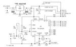
Hi, I have an LC meter that uses a standard 2x16 LCD.
It uses the D4 (11), D5 (12), D6 (13), D7 (14), ENA (6) and RS (4) pins of the LCD. They are connected to the micro. The other pins are just to power the LCD.

I also have another project that uses the same pins D4, D5, D6, D7, ENA, RS.

I want to somehow share the same LCD between both circuits. How can this be done?

I am thinking of having both circuits powered up. The first will drive the LCB with power, contrast etc. and the D4, D5, D6, D7, ENA, RS pins will be switched from one project to the other using a multi-pole switch. There might be the need to switch off the power before I switch between the two circuits, I am not sure.

Will this work?
Any other ideas, to save up switches? For example series blocking diodes?
 

Attachments

  • schem.png
    schem.png
    35.9 KB · Views: 99

Would be best if you had one microcontroller dedicated to controlling the LCD. Then, your two projects can send display data to that.
 
  • Like
Reactions: neazoi

    neazoi

    Points: 2
    Helpful Answer Positive Rating
Would be best if you had one microcontroller dedicated to controlling the LCD. Then, your two projects can send display data to that.

I can't do that now. First because of lack of programming experience, second because of limited space (fitting the second project into the first project enclosure).

I have seen some examples with series diodes and pull down resistors on the net, also some recommend data switching ICs.
But because of LCD initialization issues (and others that may arrize), it may be more straight forward to use a 6-pole switch (3x2 poles connected together) to switch between these pins.
The first project will control the PSU and LEDs of the screen. The RW pin is connected to GND on both projects. Then the rest of the pins will be switched by this mylti-pole switch. The power to both circuit should be switched off before selecting one or the other project.

How do you find this solution, given the limitations in my case?
 

You could think about using analog switches, however it is not too clear your strategy to ensure that both systems will access the LCD not simultaneously. Perhaps you could use some signal form some of these systems and check how it berhaves in order to use it to control that switch.
 
  • Like
Reactions: neazoi

    neazoi

    Points: 2
    Helpful Answer Positive Rating
You could think about using analog switches, however it is not too clear your strategy to ensure that both systems will access the LCD not simultaneously. Perhaps you could use some signal form some of these systems and check how it berhaves in order to use it to control that switch.
Simultaneous use is not needed. Switcing off all circuits, then switch the LCD lines to the wanted project, then switch on all circuits. That is what I am thinking.

Hm... with three double throat ON-OFF-ON switches for each pair of circuits, switched together, I could even share the LCD on more than two projects, as long as only one "tripplet" switch is switched each time.

- - - Updated - - -


This would be fine so that only one toggle mechanical switch is needed. However, you will need two chips, with additional power. I am thinking that the circuit will become more complex than it can with a "tripplet" switch (three double pole double throat switches, switched together). I am thinking, is this complexity (and greater size) really needed?
 

Hi,

I don´t like the idea.
In either case you need to connect the GNDs of both driving devices. I'd say continously, not switched to avoid ESD or other "out of specified range" voltages during switching.

Connected GNDs may cause problems. Even with the measurement.

Klaus
 

Basicaly, if you have 'lack of programming experience' - than this project is just not for you yet. This solution is very durty.
 

Status
Not open for further replies.

Similar threads

Part and Inventory Search

Welcome to EDABoard.com

Sponsor

Back
Top