Continue to Site

Welcome to EDAboard.com

Welcome to our site! EDAboard.com is an international Electronics Discussion Forum focused on EDA software, circuits, schematics, books, theory, papers, asic, pld, 8051, DSP, Network, RF, Analog Design, PCB, Service Manuals... and a whole lot more! To participate you need to register. Registration is free. Click here to register now.

[SOLVED] ADS rectifier circuit efficiency and impedance matching

Status
Not open for further replies.

srijan.rio

Member level 2
Joined
Mar 7, 2016
Messages
50
Helped
2
Reputation
4
Reaction score
1
Trophy points
8
Activity points
484
Hi all, I am getting a good S11 response for a rectifier circuit (<-20db at resonating frequency) but while simulating for efficiency using hb simulations, the efficiency is coming very low. What may be the cause of the signal not being transferred from input to output side ?

The same problem was posted in another thread : https://www.edaboard.com/threads/288993/. Since this is closed, I had to make a new one.

eda.png

If someone can kindly throw some light as to why this may be happening, it will be very helpful. I have attached the image of the schematic.
 

There's no DC path to the output, so the circuit can hardly work as rectifier.

The linked previous thread has a considerably different circuit, please compare.
 
Thank you for your response. Sorry for my ignorance , but by DC path you mean a resistor to the vout I presume ? I have altered my circuit like the previous thread, adding a resistance. Still the efficiency is coming very low. I have attached the changed circuit and the results. Am I doing the HB simulation incorrectly ?


eda.pngeda2.png
 

No, the problem is that the DC generated by the diode, in you circuit cannot flows since it's blocked by the C2 capacitor. You have to connect the anode to ground using for instance an inductor having a value high enough not to affect the incoming RF.
 
@albbg Thank you very much for your reply. But pardon me can you specify which anode you are talking about ? I have attached an inductor L1 of 118nH to the anode of the capacitor C2 for impedance matching. Kindly look into the results, I have posted the s11 result(less than -25 dB at resonating frequency). So doesn't it mean that the RF signal isn't being affected ?
 

L1 is ok and is used for matching purposes. You have to add another inductor from the anode of the diode to ground so that the DC current can flows through this new inductor, the diode and the through the load.
The value of this added inductor have to be high enough not to cause significant RF losses. I think a value of about 270 nH. In the simulation you can use a very large value (1 mH) to see if all is ok, but in real world you cannot, due to the self resonace frequency of the inductor.

Two other things: 50 ohms is a quite heavy load. Are you sure about it ? The other one is: I suggest you not to connect directly the cathode of the diode to the load+output cap, but putting in series an inductor to filter the residual otuput RF. In this case you have to account for its slew rate, that means it needs a while to reach the DC final value
 
Thank you very much @albbg for your guidance. Following your instructions, I was able to get a good efficiency in my circuit. Apologies for my late response.

Actually I don't have a specific load requirement for my circuit hence used 50 ohms for simulation purpose.

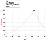
One other question if you could clarify it. The efficiency curve is getting a sharp knee point after reaching a maximum. Is it correct or the graph should have a smooth curve ? I saw two papers in net where they are getting a similar curve. Do you know what could be this reason ?eff.png.
 
Status
Not open for further replies.

Similar threads

Part and Inventory Search

Welcome to EDABoard.com

Sponsor

Back
Top