Continue to Site

Welcome to EDAboard.com

Welcome to our site! EDAboard.com is an international Electronics Discussion Forum focused on EDA software, circuits, schematics, books, theory, papers, asic, pld, 8051, DSP, Network, RF, Analog Design, PCB, Service Manuals... and a whole lot more! To participate you need to register. Registration is free. Click here to register now.

[SOLVED] op-amp attenuating the signal

Status
Not open for further replies.

preethi19

Full Member level 5
Joined
Jun 30, 2014
Messages
273
Helped
0
Reputation
0
Reaction score
1
Trophy points
16
Activity points
3,474
Hi i understand opamp for an inverting config would result in a gain in -ve with a negative output voltage and the output will be out of phase in the inverting config. While for an non-inverting config the gain is +ve and the output signal is in phase with the input. Even if the output is -ve for an inverting config the signal peak still goes upto the output's voltage value (-VCC). Though negative peak amplitude this is still not an attentuated signal. It just has a negative voltage swing. But could anyone kindly let me know when and why does an op-amp attenuate a signal. I know attenuation occurs when say the supply voltage is like 5V and we are requiring a 10V output as shown in the figure. the output saturates at 5V since it cant go beyond the supply. But say if the supply voltage can provide full output swing then at what cases do attenutation occur. I thought op-amps are only meant for amplification. What benefit do we get by an attenuated signal??? Or is attenuation not a desired factor???? Thank you!!!
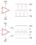
attenuate.png

Additionally i found "When using an amplifier as an attenuator, the amplifier has less than unity gain (G < 1)." Found it in this website https://www.analog.com/en/education/education-library/raqs/raq_attenuator_issue56.html

So Say inverting config provides gain less than unity. say for instance -10 gain. So does this mean signals are generally attenuated in an inverting config???. Its a bit confusing pls help!!!
 
Last edited:
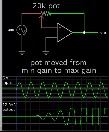
Instead of the usual diagram where two resistors set the gain, picture only a potentiometer.
Dial it so that the inverting input selects different proportions of the incoming signal versus the output signal.

6519843500_1468984405.png


It attenuates when the inverting input receives more of the output than of the incoming signal.
 
Hi,
Opamp is an amplifier by any means and the ideally has infinite gain, Vout=G*Vin is always true and the signal will never be attenuated, but can be clipped.
If the Opamp is connected in Open Loop configuration it will Amplify input signal ideally by +/-infinity depending if connected to the positive or negative pin of the device. Since the output is limited to voltage power supplies it will limit the output as shown on your second picture.
When you are connecting the Opamp with negative feedback the gain will be as follows:
Non-Inverting topology: G=1+Rf/Rin (gain is always positive)
Inverting topology: G=-Rf/Rin (gain is always negative)
In the case of negative feedback G can be set to be more then 1, in this case it will amplify the input until it will clip the output, and when G is less then 1, it will act as attenuator and will scale down the input, the polarity of the output signal is totally depends on the topology.

So if the Opamp has Gain of -10, that means it will amplify the input by factor of 10 with negative sign, for example:
Vin=0.5V, Vout= -10*0.5=-5V
Vin=-0.5V, Vout =-10*-0.5=+5V

If G=0.5
Vin=0.5, Vout=0.5*0.5=0.25V
Vin=-0.5, Vout=0.5*-0.5=-0.25V

RS
 
Hi,
When you are connecting the Opamp with negative feedback the gain will be as follows:
Non-Inverting topology: G=1+Rf/Rin (gain is always positive)
Inverting topology: G=-Rf/Rin (gain is always negative)
In the case of negative feedback G can be set to be more then 1, in this case it will amplify the input until it will clip the output, and when G is less then 1, it will act as attenuator and will scale down the input, the polarity of the output signal is totally depends on the topology.
RS

I understand we can adjust gain to be more than 1 or less than 1. But how does attenuation occur when gain is less than 1. I have attached an image. The gain is -1.5. I thought if gain is -ve then only a phase shift occurs and o/p signal doesn't saturate as long as it is within the supply range. I don't understand how signal is attenuated with a gain less than 1 which in the figure attached is -1.5. It only seems to me like gain value (-ve or +ve) doesn't matter since +ve and -ve has only to do with phase shift and attentuation occurs only with high gain values. Say for eg keeping the gain range as ( -1.5 < gain < 1.5). So when gain is not within this range attentuation occurs since output saturates. This is also what i can understand from the potentiometer example. So to sum it up "The opamp attenutates with an increased gain be it -ve or +ve gain value". Also you mentioned the signal will never be attenuated but will be clipped. Wats the difference in that.. Maybe i am confusing both the things i guess. Pls correct if i'm wrong in anything. Thank you!!!

inv.png
 
Last edited:

Why don't you understand that a gain (an increase) of -1.5 is not attenuation, it is a gain (an increase) of 1.5 times but the output is inverted (180 degrees phase shift from the input phase)? A gain of -10 is a gain (an increase) of 10 times and again the output is inverted.
A gain of +0.1 is attenuation where the output level is 1/10th the input level without being inverted and -0.1 is 1/10th attenuation but the output is inverted.

The potentiometer example shows an inverting opamp circuit. The output is always "-" (inverted, 180 degrees of phase shift) and can have lots of gain or it can attenuate.
 
Status
Not open for further replies.

Similar threads

Part and Inventory Search

Welcome to EDABoard.com

Sponsor

Back
Top