Continue to Site

Welcome to EDAboard.com

Welcome to our site! EDAboard.com is an international Electronics Discussion Forum focused on EDA software, circuits, schematics, books, theory, papers, asic, pld, 8051, DSP, Network, RF, Analog Design, PCB, Service Manuals... and a whole lot more! To participate you need to register. Registration is free. Click here to register now.

Square Wave inverter using SG3524N

Status
Not open for further replies.

Joeadeoye

Newbie level 6
Joined
Jun 16, 2016
Messages
14
Helped
1
Reputation
2
Reaction score
1
Trophy points
3
Activity points
135
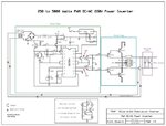
Hello engineers, I am I newbie, want to make an inverter. I am following the tutorial at https://www.instructables.com/id/250-to-5000-watts-PWM-DCAC-220V-Power-Inverter/

I was able to setup the driver stage successfully, but I am having problem with the power stage of the schematic. I used 4 Ń-channel mosfet MT3205 connected parallel, i.e. two on both sides from the driver stage.

The problem I'm having with my circuit is that, the moment I connect the battery terminal to start the inverter, the wire I use to connect the source of all the mosfet to the negative terminal of the battery will burn immediately.

When I noticed this, I increased the thickness of the wire and retest again, and now, immediately I connect the battery to start the inverter, the mosfet will get overheated immediately and get burnt instantly.

All mosfet are mounted on a large heat sink and I don't know what is causing this. Please I need help. I have burnt 6 mosfets, I can't afford to burn more...... Help

Note: I am using 12v 100Ah battery to test. My transformer is 12-0-12 primary and 220v secondary
 

Thank you for your quick response. What can I do to power my inverter? Should I substitute the mosfet for Motorola 2N3055 transistors? Or is there any other IC that I can use for oscillating?
 

MOSFET output stage isn't bad, but it should have state-of the art push-pull gate drivers.
 
OK, could you please help me with the schematic? Please...
 

The tutorial uses normal transistors. You are using Mosfets that are completely different and need a completely different circuit. You did not show us a schematic of how you connected the Mosfets.
Probably your circuit has nothing to turn off the Mosfets.
 

There is MOSFETs version of the tutorial. Here is the schematic of the mosfet version. **broken link removed**

I did my mosfet connection the same way its shown in the schematic.
 

There is MOSFETs version of the tutorial. Here is the schematic of the mosfet version. **broken link removed**

I did my mosfet connection the same way its shown in the schematic.
But the authors of most Instructables are only 10 years old and never read datasheets. The datasheet of the SG3524 shows that with the 8V supply in the original circuit the output of the SG3524 will have a minimum voltage of only 5V and the gate resistors on the Instructable reduce it to 4.5V which is much too low for Mosfets that show a gate voltage of 10V or more on their datasheets.
What is the part number of your Mosfets?
 

I used 4 N-Channel mosfet MT3205 connected parallel as shown in the schematic
 

Why didn't you look at the datasheet of the MT3205 Mosfet? It shows that with a gate voltage of 4V it barely turns on and your circuit might be feeding it only 4.5V. The datasheet shows it turning on properly with 10V that you do not have. You should use "logic level" Mosfets that are rated to turn on properly with a gate voltage of 4.5V.

Your Mosfets have high voltage and fairly low current ratings. Why not use lower voltage logic level Mosfets that are rated at a higher current?

Your (Chinese?) Mosfets cause a very high current so maybe they are cheap fakes or you connected the drain and source pins backwards?
 

I'm not a Chinese, I'm a Nigerian and I'm new to electronic stuff, I'm just a hobbyist. I have correctly connected the mosfet, first pin is gate, middle pin is drain and third pin is source. I used 10k resistor between gate and source, I connected source to ground and drain to the transformer. Inverter will only work for like 3seconds and all mosfet will explode.

I also used multimeter to measure the voltage between pin 11 and pin 14 of the Sg3524 and I got exactly 7.0v AC
 

Hee, hee. Your Mosets are probably Chinese, not you. Many Chinese parts are fakes, not you.
Your correct list of pins is what is shown on the datasheet.
Most multimeters cannot correctly measure a squarewave, a modified sinewave or a PWM wave.
 

Thanks audioguru for your time. If I may ask, what is the main reason causing my mosfet to explode? Is it that the voltage from the Sg3524 is not enough to turn on the mosfet? Or the amp of the battery is too much that is flowing through the mosfet? I am using 12v 100Ah battery, cos I notice if the wires are not even thick enough to handle the huge current from the battery the wire burns out. Pls I want to really understand what is making my mosfets explode. I have wasted 7 mosfets on this project.
 

Too small gate voltage (not turning the MOSFET fully on) can be a reason why the MOSFET overheats and is subsequently damaged. Another possible problem is overvoltage caused by transformer leakage inductance. If the stored energy is too high, it can also cause MOSFET damage.
 

I guess the problem with my project is the overvoltage from the transformer which is exploding my mosfets, because there is no load connected to the output of the transformer when I'm testing it. I guess when a load is connected, there will be no room for storing too much of energy that will explode my mosfets (I'm not sure if I'm correct). Probably I should connect a load to the output of the transformer before turning on the circuit.
 

If I may ask, what is the main reason causing my mosfet to explode? Is it that the amp of the battery is too much that is flowing through the mosfet?
No. a circuit draws as much current as it needs. A car battery can supply 600A to the starter motor in winter but the clock using the same battery draws only 0.01A or less.

You are using high voltage low current Mosfets. Try using high current lower voltage Mosfets instead.

My electricity is designed to be reliable and I never go away camping so I have never needed or used an inverter.
 

I have also tried using IRFZ46N which also explode after working for like 3 seconds
 

An IRFZ46 Mosfet also needs a gate-source voltage of at least 10V to completely turn on. But your circuit does not provide 10V. So its chip heats to a very high temperature very quickly then Kaboom.
 

Hello,
nice work how you designed PID of sg3524 i ask that from some one that was my mistake i should design my self.
 

Thanks for the clarification audio guru, I am planning to use two NPN transistor TIP122 on both side, the output from the Sg3524 will be connected to the base of the transistor to switch it on and off, then the collector will be connected to the wire from the transformer, and the emitter will be connected to the gate of my mosfet. By doing this, when Sg3524 switch on TIP122, a 12v DC current will flow from the battery, through the transformer, through the collector to the emitter and will switch on the mosfet. I guess by doing this, 12v will be sufficient to power the gate of the mosfet.

@ritesh, I used this schematic for Sg3524
**broken link removed**
F8P3ZD6H8OJF3JW.MEDIUM.jpg
 
Status
Not open for further replies.

Part and Inventory Search

Welcome to EDABoard.com

Sponsor

Back
Top