Audioguru
Advanced Member level 7
- Joined
- Jan 19, 2008
- Messages
- 9,455
- Helped
- 2,151
- Reputation
- 4,302
- Reaction score
- 2,008
- Trophy points
- 1,393
- Location
- Toronto area of Canada
- Activity points
- 59,700
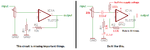
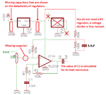
Correct, get rid of the Jfet and use an opamp and two resistors to set its gain instead.
You need to read and learn a little about opamps. Your TL072 has a voltage gain of typically 200,000 times (1/5th of a million) from DC to about 12Hz because it has no negative feedback. With negative feedback setting its gain to 10 times then its frequency response is flat from DC to about 320kHz. Your input resistors are not needed and do nothing.
You need to read and learn a little about opamps. Your TL072 has a voltage gain of typically 200,000 times (1/5th of a million) from DC to about 12Hz because it has no negative feedback. With negative feedback setting its gain to 10 times then its frequency response is flat from DC to about 320kHz. Your input resistors are not needed and do nothing.