Continue to Site

Welcome to EDAboard.com

Welcome to our site! EDAboard.com is an international Electronics Discussion Forum focused on EDA software, circuits, schematics, books, theory, papers, asic, pld, 8051, DSP, Network, RF, Analog Design, PCB, Service Manuals... and a whole lot more! To participate you need to register. Registration is free. Click here to register now.

[SOLVED] Current transformer design and debugging

Status
Not open for further replies.
At 20uS the secondary can sustain 149/20 = 7.45 volts.
But you need to subtract two diode drops from that.

Your required two volts will be well below that limit.

But Tony, for improved linearity,
isn't it a good design practice to operate any "sensing" transformer well below its maximum spec?
 

But Tony, for improved linearity,
isn't it a good design practice to operate any "sensing" transformer well below its maximum spec?
It depends what the "sensing" is to be used for.

If its for a precision current measurement or metering, then yes you might well be concerned about the last half percent non linearity. That sort of approach is pretty common in the electrical engineering and instrumentation fields.

High frequency power electronics is a bit different.
If its within a closed loop control system, or shut down current limit, as typically applied to a switching power supply, extreme accuracy and linearity is not usually a requirement. Speed of response is often far more important.

If you design some protective current limit to be say 40 amps, but the actual measured short circuit fault current ends up being 41 amps, does it really matter ?
 

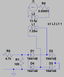
Hi. I am using the following circuit to measure the primary current of the power transformer. Output of this circuit is connected to the current limit input of a SMPS controller IC .

current_trans.png

I am having a problem with the circuit. According to the equation provided by coilcraft : RT = Vout × Nsec / Iin. Change in Rt should change the output voltage. But irrespective of the change in burden resistor from 100 to 10 ohm or to 50 ohm, my output voltage is constant at 1.2V.


How to check if the current transformer circuit is working properly. What is the test setup or test circuit that is used generally to test the current transformer circuit ?
 

You need a capacitor to hold the voltage - put a 1uF cap in parallel with the 100E resistor. Else you will never know what you are measuring...
 
Hi c_mitra. I forgot to include that in my schematic but in I have added 100nF cap across the 100 ohm resistor in the implemented circuit.
 

I feel 100nF is too low; try something that will give a RC value of about 5 times the period of the AC frequency and about 5 times the ADC conversion time. It also helps if you have some idea of the actual current being measured.
 
Either if the output is filtered (averaged rectified value) or not (instantaneous rectified value), it should be roughly proportional to burden resistor value. Reported constant 1.2 V makes no sense either. How is it measured? How's the primary current generated?
 
Hi. I changed the cap to 10uF according to your suggestion. I am measuring the DC current given to the input of the SMPS circuit. Always my DC ammeter(0 - 5A) is measuring zero, but I am getting a constant 1.2V output with the below circuit.

circuit_cur_trans_3.png

But with the change in burden resistor as according to the below circuit, I am getting an output where the current transformer is shooting upto to 5-6V with the waveform as it was shown in the first post of this thread. Here also I am measuring 0 amperes, as the average value would be close to 0A.

circuit_cur_trans_2.png

I am back to square one and I looking into the SMPS if there is any short that is causing the current transformer to shoot suddenly and turn off the SMPS controller when it starts to trigger the MOSFET.

Can you suggest why the circuit with burden resistor placed before bridge circuit is giving a constant 1.2V output. Might be it could help me debug the circuit.
 
Last edited:

I am measuring the DC current given to the input of the SMPS circuit.
That is very different to what you said in your first post
Input to the current transformer (T3) is one of the outputs of h bridge as shown in the figure before.

So is this current transformer measuring the dc going into the H bridge, or the ac coming out of the
H bridge ?
 
Last edited:

Its a queer wave form. If the invertor is meant to be switching a square wave then the Di/Dt is very fast at the transitions (hence high voltage) because the leakage inductance isolates the load, then while the pulse is running the Di/Dt slows down by a factor of 1000 or more so the induced EMF also falls. I can't see the lower value square wave at all. I would use a series R and a shunt C to reduce this edge effect pulse.
Frank
 

Hi Warpspeed. I am sorry, I meant the dc current which was measured by the DC ammeter. I hope it is clear now. Current transformer is measuring the AC coming out of the H bridge.

- - - Updated - - -

Hi Chuckey. I couldn't fully get what you were suggesting. Could you please elaborate ? Places where you mentioned lower value square wave. Which one were you meaning ?
 

If you use a common or garden audio transformer, with adequate primary and secondary inductance and tight coupling, a 1KHZ squarewave goes right through it undistorted. If you drop the frequency to say 10 HZ, you get a tilt across of the output square wave. The rising edge is OK but the trailing edge drops down in amplitude. Eventually at a lower frequency you just get a spike at the leading edges. So I had thought the pulses you could see was due to some ringing getting through and masking the actual square wave. If you say that there is no square wave at any amplitude , then the transformer looks like its got a lack of primary and secondary inductance for its working frequency. Could there be a short circuit turn somewhere? have you tested it with a 50 KHZ sine wave?
Just had another thought, the shape of the actual output current will be dependent on the other half of the H bridge, filters and load impedance. Could it be telling the truth!
Frank
 
Hi. I have to check with a 50Khz sine wave. That could be a possible way to go ahead to check how the current transformer works. I gave a load with the half the power rating of the SMPS. So I don't think it would be due to load.

This is how the SMPS is working right now, the PWM is turned on for a very brief period then the current transformer output kicks in and raises to an amplitude of around 4-5V peak which is fed to the current limit pin of the SMPS controller. The SMPS controller turns off when the voltage at the current limit pin reaches 1.2V and so the PWM stops. I thought it is due to some short circuit that current in the H bridge is raising to high level but I couldn't find any. So it is not due to some short circuiting.

Other lead that I have is that the current transformer output waveform doesn't have any change in amplitude with peaks around 4-5V with change in burden resistor from 100 ohm (linear upto 3.2A) to 10 ohm (linear upto 32A). Since I couldn't understand.
 

Recently , I have been playing about with a 50 HZ commercial current transformer and have noticed the same effect. I was changing the burden resistor to find a value for best linearity and noticed that the Vout hardly changed at all. I do not understand why it did not work as per the theory. I can only guess that in my case, the leakage inductance due to the current conductor sitting in the centre of the toroidial core, swamps the reflected impedance.
Frank
 

Hi. I am still struck with this problem and it looks like a deadlock. Could someone suggest me any direction to debug this problem. Your suggestions is greatly appreciated.

Thanks.
 

50kHz? what are the volt seconds you require out of the CT? 5V at 10uS or more? you might need a larger than average CT for this, at least 500:1 what is the max current you are seeking to sense?

dB/dT = V/NAe, so for a flux swing of 50mT say, over 10uS (half of the switching period, 1/50kHz) and 5V required (quite large) and N=500 say, then the core must be at least 2 x 1mm, so for a 5x5 EF20 core (common) the flux will be in bounds,

This assumes your power circuit is an H bridge or 1/2 bridge where the current flows as true AC in the CT allowing you to rectify it and add a burden resistor, so for 10Apk for the single turn primary, there will be 20mA in the sec, and the R will be 250 ohm for 5V,
For a single ended power stage, you have a single diode (u-fast 200V min) and your burden, but you must allow a reset time for the CT, so the duty cycle must be limited to 85-90% say for this (due to the capacitance of the CT winding affecting the reset time)
hope this helps...
 
50kHz? what are the volt seconds you require out of the CT? 5V at 10uS or more? you might need a larger than average CT for this, at least 500:1 ...

Very correct. Also a single fast low drop diode for rectification and a small capacitor for holding the potential: that is all that are needed.

5V will be absolute maximum; typical voltages will be around 2-3V and I would suggest designing around 1-2V typ.

You should be able to resolve 0.05A without a fuss.
 
Hi. Thanks a lot for your replies. I am currently having 3 versions of current transformer from coilcraft with the maximum no of turns being 200 and Voltage second product for it being 596 VuSec. I am now using 1N4148 and I am planning to shift to schottky diode. One that I am having with me is 1n5819 and it is having 600mV Forward voltage drop. Can you comment how good is the diode selection and as well suggest diodes which you think which are better than this.

I want the SMPS design to have maximum of 6A current rating. The current transformer output should be 1.2V [SMPS controller turns off if any voltage higher than this is applied] at 6A. If I assume maximum input current is 10A, at 10A output voltage is 2V. So my burden resistor should be 40 ohm. I hope I got your point correctly. Other thing about the flux swing, according to the voltage second product to its frequency, I get a value 29.8 V (596VuSec/20uSec = 29.8V). So I can say that CT will be linear till 29.8V. Can you guys correct me if I am wrong. Your help is greatly appreciated.
 

one cannot use a cap in place of a burden resistor on a CT, 0.6V for a diode is about the lowest you can get, it does not pay to run a CT to its full VuS rating, the voltage on the CT sec is the sum of diode drops and burden IR drop...
 
Thanks Easy peasy. Can the cap be placed in parallel with the burden resistor ? I will use that diode then. I don't want to run it to its full VuS rating but just have shown the maximum theoretically possible voltage. I will try it out and let you guys know.
 

Status
Not open for further replies.

Similar threads

Part and Inventory Search

Welcome to EDABoard.com

Sponsor

Back
Top