Continue to Site

Welcome to EDAboard.com

Welcome to our site! EDAboard.com is an international Electronics Discussion Forum focused on EDA software, circuits, schematics, books, theory, papers, asic, pld, 8051, DSP, Network, RF, Analog Design, PCB, Service Manuals... and a whole lot more! To participate you need to register. Registration is free. Click here to register now.

[SOLVED] PIC 16f877A not working in circuit

Status
Not open for further replies.

sonar_abhi

Member level 1
Joined
Mar 15, 2016
Messages
36
Helped
2
Reputation
4
Reaction score
2
Trophy points
8
Activity points
380
Hello Guys,

I am making a simple program to test the pcb I designed.

The program is to turn on a led at PORTC.F3. The PIC16f877A works fine in the development board but it wont work in the actual pcb. I have checked the connections and they seem to be fine.

I dont know what is wrong. I am posting a snapshot of the PCB. Please help.
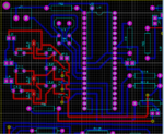
PIC%20PCB%20Snap.png
 

Hi,

it seems to b a two sided PCB layout. Why don´t you use a GND plane?

I even can´t find electrolytic bulk capacitors and fast ceramic capacitors at VCC.

Klaus
 

Hi,

I am an amateur at board design. This is my first attempt at pcb etching. Hence coudnt pay attention to GND plane. I just went ahead with the general circuit design that is shown in theory. Is the absence of GND plane causing problems? Cause I am getting a minuscule voltage reading of about 0.50 V at the port.

What can I do to rectify the error?

Thanks
 

@easyrider, I know. I am an amateur in terms board design.

@Klaus, I didnt realise the absence of GND plane would cause such problems.

I am getting a minuscle voltage of 0.50 V at the port but on the development board it is working as it should. How can I rectify the error?

Thanks
 

Hi,

imagine a wire to be a rope. There are short and long wires and narrow and thick wires. Now imagine dancing on a rope.
The shorter and the thicker it is the more solid or stable it is.

But a GND plane is like a solid floor. It doesn´t move, you can rely on it.

Like a rope moves, similar the voltage moves on a thin wire.
And like a solid floor the voltage of a GND plane is reliable and doesn´t move.

Now there are electromagnetic waves (EMC) in the environment. It is like wind when you dance on a rope. It will make you dangling.
But if you stand on solid floor (GND plane) the wind won´t harm you that much.

*****

I don´t know where you measure (and to what reference) the 0.5V, but it is very likely, that with a GND plane you will see only some mV.

Klaus
 
Got it. Will take care designing the next board. Meanwhile, can this board be used with some modifications? Or the absence of the Ground plane has rendered it useless?
 

would you plz attach ur circuit ? so we can help fixing your board

search for my post "need help starting with 16f877" & see how bad a board i use with wires & its ok
 
Last edited:
I assume you are programming the chip somewhere off-board. Also I assume 'J1' is the power supply feed that is providing a fully regulated voltage to the board.
What I don't see are any by-pass capacitors on the supply lines.
Are you sure the crystal is oscillating and the program is actually running?
How are you measuring the 0.5V on the pin?
Susan
 

I don't think that the absence of a ground plane is your problem, as I have built similar circuits using the PIC16F877A on Vero board. Try running your circuit at 4Mhz and see if it works, please add the decoupling on the supply rails. Are you sure that you have set the configuration bits correctly, the watch dog timer to off and set the correct oscillator type
 
Hello all,

I rebuilt the PIC and the oscillator circuit on a vero board and connected it to the original board, and it is working just fine now.

Will take care of adding the ground plane the next time while designing the pcb. Thanks for everybody's help
 

Status
Not open for further replies.

Similar threads

Part and Inventory Search

Welcome to EDABoard.com

Sponsor

Back
Top