Continue to Site

Welcome to EDAboard.com

Welcome to our site! EDAboard.com is an international Electronics Discussion Forum focused on EDA software, circuits, schematics, books, theory, papers, asic, pld, 8051, DSP, Network, RF, Analog Design, PCB, Service Manuals... and a whole lot more! To participate you need to register. Registration is free. Click here to register now.

Bi-directional amplifier (font end) for VHF hand-held

Status
Not open for further replies.

AndreyG

Full Member level 4
Joined
May 10, 2010
Messages
196
Helped
27
Reputation
54
Reaction score
27
Trophy points
1,308
Location
Vancouver, Canada
Activity points
2,946
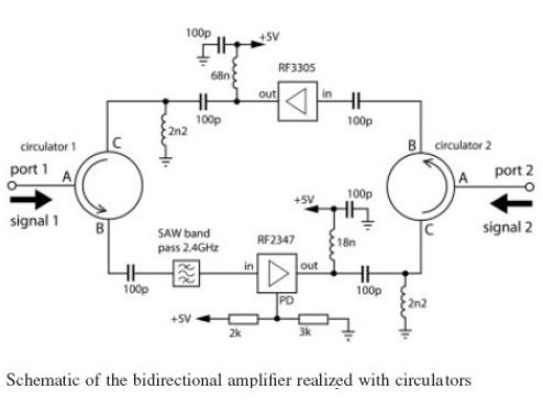
How to make VHF 'Antennafier' = bi-directional amplifier installed next to antenna terminals?
The only practical solutions I found either require Tx/Rx switching (requires control line that my radio does not have) or circulators that at VHF are large and expensive.

Are there any other practical solutions?
 

You do not need a control line, you can feed DC up the coax feed. Couple the inner to your control signal via radio frequency chokes, decouple the control line to RF. Voila you have a low speed/DC control line up to the top of your mast.
Frank
 

Thank you for your comment Frank,
The complication with that: I plan to use hand-held unmodified and as such it does not have control signal output - only RF connector. I think I can use detector to detect carrier frequency when press PTT button. But I see in some references that this is is an ancient method (RF sensing Tx/Rx switch) and not recommended.
 

.................I think I can use detector to detect carrier frequency when press PTT button. But I see in some references that this is is an ancient method (RF sensing Tx/Rx switch) and not recommended.

RF sense switching is very acceptable for AM and FM transmitters and works very well ... have use it on a number of amplifiers over the years

is your TX-RX amplifier system going to be close to the output of the handheld or remotely located at the far end of the coax ?
If remote, then you still have the hassle of DC supply to the amplifiers ... if local to the handheld, then it's easy to achieve


OK found the circuit for my Dick Smith 100W 2m amplifier
everything inside the red box is the RF sense and switching ... C1 a 1pF cap in the lower left couples incoming RF from the amp input to the rectifier diode
that is then used to turn on transistors and switch the relay


that should get you started :)
 

Attachments

  • amp switching.GIF
    amp switching.GIF
    196.5 KB · Views: 157
Is impossible to make without switches an RX & TX bidirectional amplifier working on the same frequency.
If RX and TX are on different frequencies (as the repeaters are) you can use duplexers to separate the paths, but not if they are on the same frequency.
 

Thank you for sharing the schematic, this helps. I am wandering why you do not use band filter - I was thinking to install band pass filter in front of the detector - would it be right thing to do?
 

Is impossible to make without switches an RX & TX bidirectional amplifier working on the same frequency.
If RX and TX are on different frequencies (as the repeaters are) you can use duplexers to separate the paths, but not if they are on the same frequency.

Impossible? Possible but not always practical. Consider schematic below.


AndreyG,
As you said earlier, circulators become large at VHF frequencies. Replacing the circulators with directional couplers has disadvantages too.

GE


This is very interesting idea as well. I followed the link you suggested and it shows exactly the bi-directional amplifier circuit. Such circuit will be simpler then circuit with carrier detection and switching. The question is: at VHF will hybrids offer enough isolation to combine amplifiers with 20+ dB gains (LNA and PA). Not clear. I understood transformer-based hybrids are used for telephony - low MHz.
 

I would not bet any money on the bidirectional amplifier using circulators.
The schematic looks good only on paper, but in practice, if the in/out frequencies are identical, the circuit will oscillate like something never seen before.
Even the author of the original article mention this:

"The forward and reverse gain dropped down to ~5 dB within the ISM band. The reflections at ports 1 and 2 are positive and show values of +5 dB within the ISM band. Moreover, two significant resonance peaks are observed, one at 2.37 GHz and the other at 2.59 GHz. This indicates that this bidirectional amplifier is highly unstable."

**broken link removed**

OK, he mention later that he can compensate this instability from the layout design, but as I said, I would not bet on this approach.
 

Status
Not open for further replies.

Part and Inventory Search

Welcome to EDABoard.com

Sponsor

Back
Top