Continue to Site

Welcome to EDAboard.com

Welcome to our site! EDAboard.com is an international Electronics Discussion Forum focused on EDA software, circuits, schematics, books, theory, papers, asic, pld, 8051, DSP, Network, RF, Analog Design, PCB, Service Manuals... and a whole lot more! To participate you need to register. Registration is free. Click here to register now.

[SOLVED] Wireless energy transfer inductive link and resonance

Status
Not open for further replies.

SK245230

Member level 3
Joined
Nov 24, 2015
Messages
57
Helped
3
Reputation
6
Reaction score
3
Trophy points
1,288
Activity points
1,844
I have readed in many articles that for high coupled inductors (high k) you get a better efficiency using non-resonant inductive link. On the other side, for low coupled inductors (low k) you get a better efficiency using a resonant inductive link.
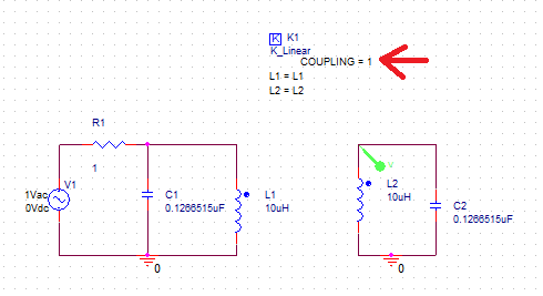
So I wanted to check this information through a simulation on LTSpice. Below you have two designs, one resonant and one non-resonant designed for 100kHZ.
TF1.png
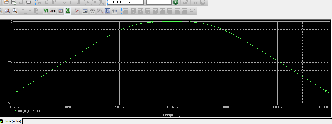
I have simulated the efficiency for high k=0.8, blue curve=resonant, yellow=non-resonant
TF2.png
For low k=0.1
TF3.png
As expected at low k, you get a better efficiency for non-resonant. But for high k, non-resonant has almost the same efficiency as resonant.
Is it normal or am I missing something in my model? Why do we use only non-resonant inductive link for high coupled inductors?
 

On the other side, for low coupled inductors (low k) you get a better efficiency using a resonant inductive link.

Few lines further I read this:
As expected at low k, you get a better efficiency for non-resonant

Am I missing something?

- - - Updated - - -

This is what FvM said once:
Not at all. Setting K=1 makes the two inductors behave like one.

At high K, your inductors behave like one, so your calculations for the resonance are history.
 

Sorry I wanted to write: As expected at low k, you get a better efficiency for resonant. This is what you can see on the blue curve for k=0.1, you get an efficiency of 96% @ 100khz.
 

To be more specific, resonance refers specifically to nulling out the leakage inductance(s) which would normally inhibit power transfer. When k is near 1, the leakage inductance is negligible, so there's basically nothing to resonate with.
 

Simulate this and see what happen.

On the resonant circuit(second circuit), with high K, change the 240 nF capacitors by 0.1266515 uF capacitors and let me know what is the result please.

Not with series resonance, change the 2nd circuit to parallel resonance. place 10 uH || 0.1266515 uF in the Tx and in the Rx.
 

Ok If understand well, if you take a resonant circuit and you bring it in high coupled mode, it will work as a non-resonant circuit. (this is why the blue and the yellow curve are almost the same in the simulation at k=0.8)
But then I don't understand why all those alliances (AirFuel and WPC) distinguish resonant/non-resonant and tells you the benefit of one or the other? I mean you could just build a resonant circuit and it will become non-resonant when high coupled.
 

But then I don't understand why all those alliances (AirFuel and WPC) distinguish resonant/non-resonant and tells you the benefit of one or the other? I mean you could just build a resonant circuit and it will become non-resonant when high coupled.
Hard to say without reading the original claims you're referring to. But in principle resonant drive should always be better (assuming the resonant capacitors have no loss), since it minimizes reactive power flow. But when K is high then the advantage likely becomes negligible.
 
  • Like
Reactions: CataM

    CataM

    Points: 2
    Helpful Answer Positive Rating
to CataM:

Well, when I add your capacitor of 0.1266515µ, the curves become the same, resonant and non-resonant at k=1. Is this what you wanted me to see? How did you find this value?
 

There is no peak in the 100 kHz freq?

At K=1, the 2 inductive coils behave like one, so I wanted to see if there is resonance. I calculated the Capacitor to place in parallel by equaling the Capacitor reactance Xc(f) with the inductor reactance XL(f), and i got C=1/(4Π^2*f^2*L)=2.533*10^-(7), but when k=1, as they are one, the coils will have both capacitors in parallel, which capacitance is summed, so I divided 2.533*10^(-7) by 2 and get the capacitance 0.1266515 uF.

- - - Updated - - -

This is what I meant.


Ok I think I have understood. I was confused about the wireless power consortium who was promotting the non-resonant link for his Qi standard. I thought the choice of resonance/non-resonance was based on performance, but in fact it's only a choice of application.
 
  • Like
Reactions: CataM

    CataM

    Points: 2
    Helpful Answer Positive Rating
Ok I think I have understood. I was confused about the wireless power consortium who was promotting the non-resonant link for his Qi standard. I thought the choice of resonance/non-resonance was based on performance, but in fact it's only a choice of application.
That is pretty much it.

Extreme close coupling, as in a conventional transformer is always non resonant and the results are much more predictable.

Way below critical coupling where considerable relative distances and very loose coupling are involved, resonant operation will be better where both tuned circuits can resonate and be tuned to a peak independently without mutual interference.
 

Status
Not open for further replies.

Similar threads

Part and Inventory Search

Welcome to EDABoard.com

Sponsor

Back
Top