Shahendaeid
Junior Member level 1
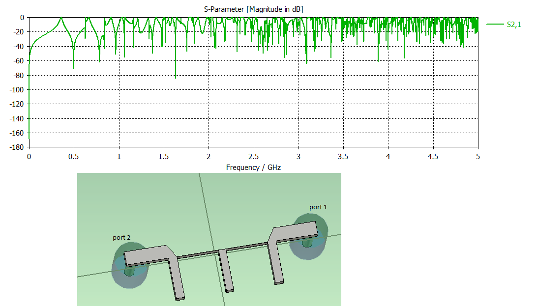
Microstrip filter simulation
I was trying to make simulation for LPF example in Pozar .but during the simulation I found these errors
[1]At least one propagating mode is not considered at port 1.
[2]Mesh adaptation terminated because the maximum number of passes is reached.
I could not solve them so I could not get the result as found in the book
Awaiting replies,
Regards