Continue to Site

Welcome to EDAboard.com

Welcome to our site! EDAboard.com is an international Electronics Discussion Forum focused on EDA software, circuits, schematics, books, theory, papers, asic, pld, 8051, DSP, Network, RF, Analog Design, PCB, Service Manuals... and a whole lot more! To participate you need to register. Registration is free. Click here to register now.

choosing transistor pair in layout

Status
Not open for further replies.

preethi19

Full Member level 5
Joined
Jun 30, 2014
Messages
273
Helped
0
Reputation
0
Reaction score
1
Trophy points
16
Activity points
3,474
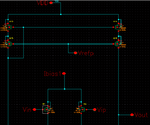
Hi all i have attached two images. One schematic and layout. I am learning to do layout and this is an eg. We can see transistor M1,M2,M13,M14,M15 and M16..could anyone pls explain to me why they have paired M1 and M2 together, (M13 M14) and M15 M16... My doubt is now if i want to do layout how am i supposed to know how to pair up the transistors and do layout. I could have paired M13 and M15 too right??? Is der any dependency or any factor that should be considered when we choose to keep two transistors near one another paired?? Becoz if dimension is a factor then M13 and M15 also have same dimensions. Can someone pls help!!!
sch.png


lay.png
 

Your mosfets are arranged to do similar functions as many schematics which are posted at this forum.

M 1-2 are arranged as a long-tail pair.

M 13-14 is arranged as a current mirror. M 15-16 looks as though it applies an adjustment voltage to the current mirror.

The challenge in manufacturing, is to fabricate the mosfets so they match in their performance.
 
Today's IC design generally makes use of fully differential architectures. In that case, all the P and N counter parts have to be matched correspondingly, like input pairs, load pairs, cascode pairs and so on. Also, in the case of current mirrors, all the current source transistors need to be matched to their diode connected transistors.

Matching (keeping the transistors together with common centroid or interleaving architectures) ensures that the device parameters be the same for the matched devices and helps to nullify the process gradients to a certain extent. So, the transistors which are supposed to do the same function are to be matched in the layout.
 
Last edited:
... pls explain to me why they have paired M1 and M2 together, (M13 M14) and M15 M16...
Because of similar functionality, s. BradtheRad above.

I could have paired M13 and M15 too right?
You could, but this is not so important: their functionality is different: CS & CG configuration.

Is der any dependency or any factor that should be considered when we choose to keep two transistors near one another paired?
Again: same functionality.

Becoz if dimension is a factor then M13 and M15 also have same dimensions.
Same dimensions isn't decisive, same functionality is. M13 and M15 ain't necessarily have the same dimensions. In most cases of such a cascode current mirror, they haven't.
 
A current mirror involving two transistors is taken as a pair and laid out. But in my case i have current mirror with 3 transistors. So can i pair up all 3 together???? Will it be right way to do it??? Thank you!!!!
 

Yes, you can group those three transistors and lay them out.
 

Thank you for the reply. But my problem in the 3 transistor current mirror is that they have different drain connections. So i can do like D G S G D.... So here source is common for two transistors and drain of two transistors in the current mirror is different. But if i have to add 3 then it will become D G S G D G S..... So in this in the end the drain of 2nd and 3rd transistors are shared. So making a connection to drains of 2nd and 3rd transistor... Is there any better way to pair them up.. If using dummies is a suggestion i have no idea on how to use them. As in i know dummy is nothing but extra gate and drain source but wer am i supposed to connect the dummies in the circuit and by adding dummies to the ckt won't it cause a change in the desired function of the ckt becoz in a way it isn't it just like adding another transistor??? Thank you!!!
 

Actually you have 6 transistors (if you still cling to the schematic in your 1st post). Why don't you take its corresponding layout in your own post? All transistors with the same function are very well common-centroid paired (diagonally cross-mixed), and I don't think you can make a much better layout. If you just need the current mirror part (4 transistors), the right side part of the layout is fine. See e.g. this paper: View attachment Current_Mirror_Layout_Strategies_for_Enhancing_Matching_Performance.pdf
 
Status
Not open for further replies.

Part and Inventory Search

Welcome to EDABoard.com

Sponsor

Back
Top