Continue to Site

Welcome to EDAboard.com

Welcome to our site! EDAboard.com is an international Electronics Discussion Forum focused on EDA software, circuits, schematics, books, theory, papers, asic, pld, 8051, DSP, Network, RF, Analog Design, PCB, Service Manuals... and a whole lot more! To participate you need to register. Registration is free. Click here to register now.

Reading current from 100amp/50Mv shunt

Status
Not open for further replies.

wizpic

Advanced Member level 3
Joined
May 23, 2004
Messages
787
Helped
108
Reputation
216
Reaction score
72
Trophy points
1,308
Location
London
Activity points
6,334
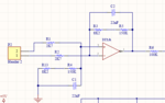
I need to measure current and display it on LCD, I have a 100amp shunt with 50mV output I have an op-amp set with a gain of 100 and my maths tell me that at 100amps the resistance is 0.0005 so
100/50=0.0005 example 75amps flowing through the shunt = 75*0.0005 = 0.0375(37.5Mv) with a gain of 100 that = 3.75V voltage reading. I'm using a ADS1115 (16bit) ADC converter and have the voltage readings displaying correctly, Which is reading correct at 75amps I get 37.5V on my fluke meter measuring at the shunt terminals and 3.75V on the output of the op-amp(give or take a bit), But the bit I cannot get my head around or so to speak I can't see the wood through the tress is how to work the maths out how to work the maths out to display 75amps on the LCD, The more I read or try working out the maths the more I seem to get confused
Could someone give me a few pointers to be able to understand or work it out as I would like to work it out correctly and understand it better rather than trying to add a fudge figure (botched figure) in the equation to get it to display the correct value like I have done in the past because it was easier to do and I found when I did but altered the current flowing the readings did not match by adding the fudge figure.
Thanks
 

hello,

your request is not very clear !

I'm using a ADS1115 (16bit) ADC converter and have the voltage readings displaying correctly,
Which is reading correct at 75amps I get 37.5V

with your ADC 16 bits , you get a raw value in points ... not a value in volts !
so it seems you allready use a conversion factor to transform your raw value ( binary result of ADC conversion) in volts..
and i think, at least you want a result in Amps (physical unit).

The key point is : what raw value do you get when apply 75 Amp in your shunt ?

Post all information
schematic
MCU type
code (program)
compiler type

ADC config
PGA gain
Power supply
 

I'm using Arduino
here is the code
Code:
#include <Wire.h>
#include <LiquidCrystal_I2C.h>
#include <Adafruit_ADS1015.h>
Adafruit_ADS1115 ads1115;
#define ADS1115_REG_CONFIG_DR_860SPS
#define AVG_NUM 24   //Number of samples to take for ADC reading
#define VOLTS_CHAN0 0 //Batteryv oltage 1
#define VOLTS_CHAN1 1 //Battery voltage 2
LiquidCrystal_I2C lcd(0x27, 2, 1, 0, 4, 5, 6, 7, 3, POSITIVE);
Adafruit_ADS1115 ads;  /* Use this for the 16-bit version */
float Vresults0; // battery voltage
float Vresults1; ///Amps reading
float Vresults2; //only temp will be removed
float Vresults3; //only temp will be removed
float Vresults4; //only temp will be removed
float Vmultiplier = 0.000188;  // used to convet readings this is calculated 
float R1 = 9960.5;    // !! resistance of R1 !!
float R2 = 2700;     // !! resistance of R2 !!


void setup() {
  ads.setGain(GAIN_TWOTHIRDS);  // 2/3x gain +/- 6.144V  1 bit = 3mV      0.1875mV (default)
  ads.begin();  //start the 16bit A/D converter
  Serial.begin(9600);                           // Initialize Arduino to PC Com Port(debug only to be removed on fianl build)
  lcd.begin(20, 4);                              // Initialize the LCD.
  lcd.clear();
  delay(100);
  lcd.setCursor(0, 1);
  lcd.print("Initializing...");                  // Print something on the display to show will be removed debug only
  lcd.setCursor(0, 2); // Print something on the display to show will be removed debug only
  lcd.print("Daves Van Meter"); // Print something on the display to show will be removed debug only
  lcd.setCursor(0, 3); // Print something on the display to show will be removed debug only
  lcd.print("By Dave"); // Print something on the display to show will be removed debug only
  delay(1000); // Print something on the display to show will be removed debug only                                   // it's working.
  lcd.clear(); // Print something on the display to show will be removed debug only                                   // Clear display
  delay(100);

}

/* ========== Main Loop ============================================================= */

void loop() {
  read_data();                                              // Get current and voltage values.
  write_to_lcd();
  //This shall be removed only here for debuging and getiing it working.
  Vresults3 = Vresults0 / (R2 / (R1 + R2)); /// This will be removed and replaced only for testing
  Vresults4 = Vresults1 * 10; //this is wrong 3.75V shows 37.52amps *100 shows 375.2amps

}


/* ========== dsiplay the data ============================================================= */
void write_to_lcd() {
  lcd.setCursor(0, 0);
  lcd.print(Vresults0, 3); lcd.print("Raw V");
  lcd.setCursor(11, 0);                              //
  lcd.print(Vresults1); lcd.print("Raw A ");
  lcd.setCursor(0, 2);
  lcd.print(Vresults3); lcd.print(" Actual V  ");
  lcd.setCursor(0, 3);
  lcd.print(Vresults4); lcd.print(" Actual A  ");

}

/* ========== read easch channel 24 times ======================================================== */
int read_adc(int channel) {
  float sum = 0;
  int16_t temp;;
  int i;

  for (i = 0; i < AVG_NUM; i++) {      // loop through reading raw adc values AVG_NUM number of times
    temp = ads.readADC_SingleEnded(channel);        // read the input pin
    sum += temp;                       // store sum for averaging
    delayMicroseconds(50);             // pauses for 50 microseconds
  }
  return (sum / AVG_NUM);              // divide sum by AVG_NUM to get average and return it
}
/* ========== read chanel ============================================================= */
void read_data(void) {

  Vresults0 = read_adc(VOLTS_CHAN0) * Vmultiplier; //(R2/(R1+R2));    //(R2/(R1+R2)This will replace above calcultaionvoltage reading
  Vresults1 = read_adc(VOLTS_CHAN1) * Vmultiplier ; // current reading.

}
op-amp sample.PNG
Sample of the op-amp set up, The 100K pot will be replaced with fixed 100K resistor, the other pot is for setting zero point plus pin 4 should go to -5V but I only use this a quick setup an sim , The idea is I have a pot on A1 of the ADS115 breakout board to give the 0-5V so with the input set to 37.5Mv output would be 3.75V so with the pot set to 3.75V I need it to display 75amsp. Bench testing at the moment but once I have it near working I shall take it into the workshop for real testing and add all the calibration routines then as it's only part of a project but thought I would get this part working first in stages. The actual voltmeter side is showing the values as it displays on my fluke meter with just adjusting the R1 value has the resistor is only 1% but will switch to 0.1%
 

hello

give what result do you get with Raw data (in points)
for Vresults0 and Vresults1
then , after apply the correct mutiplier for V unit or Amps unit ..

Code:
void read_data(void) {

  Vresults0 = read_adc(VOLTS_CHAN0) ;
  Vresults1 = read_adc(VOLTS_CHAN1);

}


void loop() {
  read_data();                                              // Get Raw data for current and voltage  
  write_to_lcd();
  //This shall be removed only here for debuging and getiing it working.
  Vresults3 = Vresults0  *  Vmultiplier;                       //  value in volt  (3,75V ?)
  Vresults4 = Vresults1  *   Vmultiplier * 20.0 ;            //  value in Amps (  3.75 *20 =75 amps)

}
 
  • Like
Reactions: wizpic

    wizpic

    Points: 2
    Helpful Answer Positive Rating
How did you come up with 20 ?? It's seems to work with the pot on the test bench,
I will add the other 2 remaining channels to the pot's to get the 16bit value, What I meant by the raw data it what the actual pot read from 0-5V and not the 16bit result

will see how it works when I get it hooked to the main part in the workshop
 

How did you come up with 20 ?

if your Vmultiplier can scale the raw value of ADC reading when you enter 37,5mV and show a result of 3,75V
to get 75 instead of 3,75 simply multiply by 20 ! 3,75* 20 => 75

ADC means Analog --> to --> Digital , so Raw data is a digital value (binary result) .. not volts.
When using ADC conversion , the 1rst step is to Know what raw value (16 bits) deliver the ADC for a known voltage input..
After you can convert in Physical Unit (Volt,Amper,°C...) it is only a mathematik calculus..
 

'
if your Vmultiplier can scale the raw value of ADC reading when you enter 37,5mV and show a result of 3,75V
to get 75 instead of 3,75 simply multiply by 20 ! 3,75* 20 => 75

ADC means Analog --> to --> Digital , so Raw data is a digital value (binary result) .. not volts.
When using ADC conversion , the 1rst step is to Know what raw value (16 bits) deliver the ADC for a known voltage input..
After you can convert in Physical Unit (Volt,Amper,°C...) it is only a mathematik calculus..
The 3.75reading comes from the op-amp which has the gain of 100, the0.000188 is the part that converts it 0-5v so I do understand what adc is. It reads correct in bench like I said. I knew it would be simple in the end guess I give it to much thought. But still don't understand how you plucked 20 to come to the correct figure I was trying that way with different numbers but thought I was just adding a fudge factor
Will see how it goes
 

Sorry, there was some misunderstandanding from myself ..


what i understand now:

you use the ADC with a PGA Gain=2/3
so full scale is +-6.144V
and +6,144V -> 32767 points
6.144/32767 => 0.0001875 your Vmultiplier..

and you want to use an external Analog amplifier ( instead of internal PGA) to
amplifie 37,5mV up to 3,75V
so if ADC see 3,75V ADC deliver 20 000 points (= 32 767 * 3.75 / 6.144)
if you want to scale to 750 ( and get 1/10 amp of resolution)
20 000 / 750 =26.66
so scaling value is
shunt 37.5mV -> Analog amplifier *100 -> 3.75V -- ADC reading -> 20 000 points / 26.66 -> 750 (1:10 of Amps)
or divide by 266 if you want Amps, without decimal

Question :
why you don't use PGA gain=16
256mV for 32767 points -> 4800 points for 37,5mV
just scaling with 4800/750 => 64
ADC result / 64 to get 750 dizieme d'Ampere
Thanks that makes it more clearer and understand now, The reason I don't use the PGA because the I'm using A0 for voltage with a resistor divider to scale 20V max to 0-5V and A1 for the current and I would presume that this would effect the voltage reading if I set it to that on setup, I guess I could use a bigger resistor divider and to make the voltage smaller then use the PGA with 16 gain scale. I will have to read up more on the data sheet as this is the first time I've used this ADS1115 board. I use to use PIC'S but thought give Arduino a bash. The code works but could well and more than likely be improved on for better performance.
 

I'm trying a different approach now, The other way worked well but I need to measure current flowing in and out but only using one shunt in another project, I have the circuit below set up using a op-amp as a differential mode and if my maths are correct this is a gain of 58.6 using 70amp 75mv shunt with 2.7mV across the shunt with 2.52amps flowing and I get 162.4mV (should be 158.2mV) on pin 1 how would I convert this to read 2.52 on the LCD.
If I get 35amps flowing my maths work out the output to be 1.401volts on pin 1, I've tried your method but the results are strange, I don't understand where you get 750 from. if I place /266 I only get 28 on the display I thought it would of read 35 and /26.66 it reads 279.89
The circuit below is only part of but all the other part does it makes sure that it's always positive output when current flows the opposite direction.

I think it's me been dumb again :)
 

Attachments

  • dif op.PNG
    dif op.PNG
    11.5 KB · Views: 121

I don't understand where you get 750 from

in your previous post , it was not the same shunt and scale Amps : 50mV for 100Amps
so with 37.5mV -> 75 Amps or 750 *Amps/10 !

now you have un shunt for : 70Amps -> 75mV .. so change the rule ...

what is the reference of your AOP ?
is it a rail to rail model ?
what is the power supply of AOP .. 5V ?


What is your AOP output, when 0 mV on shunt ?
 
Last edited:

Your amplifier is not linear because too big offset value when 0mV on shunt..
it is better to use a symetrical power supply +5 -5V for the AOP..
this is a simul , but can confirm the problem
with +- 5V OV offset is just 86µV ..

get a good response with your AOP ..before to do scaling with ADC

Ampli_shunt_rev.jpg
 
  • Like
Reactions: wizpic

    wizpic

    Points: 2
    Helpful Answer Positive Rating
Your amplifier is not linear because too big offset value when 0mV on shunt..
Fortunately, offset is a linear error quantity, so that it can be easily adjusted.
 

Your amplifier is not linear because too big offset value when 0mV on shunt..
it is better to use a symetrical power supply +5 -5V for the AOP..
this is a simul , but can confirm the problem
with +- 5V OV offset is just 86µV ..

get a good response with your AOP ..before to do scaling with ADC

View attachment 123171
Yeah the shunt has changed second project because the 100amp shunt is been used in the other project which is on soak test and this is the only shunt I have to hand
Sorry forgot to say it runs off a-5 & +5v supply. The output is 0 from the op-amp with no load. I placed a current draw of 2.53 and 5amps through the shunt I get 0.165mV @ 2.53amps and 345mV @ 5.32amps. After doing some playing and searching this is the maths I came up with where it displays the correct current. My maths worked out if I understood it correctly the gain set up from the op-amp is 58.6 so using this formula
Amps_sclae =(1/(58.6 *0.001)) = 17.06 so 0.345 *17.06 =5.88amps but current clamp reads 5.32amps so this worked amps-scale =(1/(64.8*0.001) = 15.43 so 15.43*0.345=5.33amps. The 0.001 is the calculated shunt resistance.
I'm not sure if that is the correct way of working it out or I have the correct op-amp gain future but just kept adjusting amps_scale until it read correctly
I have gone about it the correct way ?
 

OK..
if your AOP is linear and with a Gain=58.6 ,
you will get 3.45V at 53.2Amps

and 3.45*1024/5.0=> 706 points read by ADC
so scaling is 706/532=13.28
706 / 13.28 will give the resilt 532 in 1/10em of Amps so place the decimal point to read 53.2 on LCD

Amps*10= Adc_Reading / 13.28

with this gain on AOP, your maxi Amps will be limited at 771 => 77.1 Amps , not 100.0 Amps !

coul you check and confirm this calculus ?
 
  • Like
Reactions: wizpic

    wizpic

    Points: 2
    Helpful Answer Positive Rating
OK..
if your AOP is linear and with a Gain=58.6 ,
you will get 3.45V at 53.2Amps

and 3.45*1024/5.0=> 706 points read by ADC
so scaling is 706/532=13.28
706 / 13.28 will give the resilt 532 in 1/10em of Amps so place the decimal point to read 53.2 on LCD

Amps*10= Adc_Reading / 13.28

with this gain on AOP, your maxi Amps will be limited at 771 => 77.1 Amps , not 100.0 Amps !

coul you check and confirm this calculus ?
Remember I'm using 16bit and not 10bits . At 70amp current draw full 75mV I calculate 4.39v output. This project will be 50amps max not like the other where that is 80amp max that's why I used 100amp shunt, sorry for the confusion I will soon be able to test it at 50-55amps as where I am at the moment limited to 25-30amps will try this tomorrow if time permitted, In working maths out 4.39*15.43 =67.74 not quite the 70amps as I expected.
Have I worked out the op-amp gain correctly which is another question ?
Thanks for taking the time to help very much appreciated
 

Just thought I'd give an update
I have found a flaw in this design, I forgot when I designed my op-amp circuit it was based on 60mV shunts and not 75mV shunts this is was where I was getting my errors from. The output of the op-amp peaks at 3.720volts with 60Mv input from the shunt this where the short fall was from with the 75mV shunt. The gain of the op-amp is 58.6 and calculating the shunt resistance example at 60Mv produced by the shunt divided by 100amps =0.0006millohms and with this equation (1/(58.6*0.0006)= 28.44 so this is the gain factor to scale the amps.
So set it all up on the bench with a 10K pot setup to produce the 0-60mV to feed into the op-amp, So let's say we have 30mV input with an output from the op-amp of a calculated voltage of 1.76 actual is voltage is 1.741(close enough) then we times this by our gain factor 28.44 * 1.741 = 49.51amps. I've tried the same set up for a dummy 60amp 60mV shunt, .060/60 = 0.001, Scale_gain =(1/(58.6*0.001) =17.06, Same test set at 30Mv input I get 1.741 on the output 17.06*1.741=29.70 still close enough. I had a 60A 60Mv shunt to hand tried this on the workshop bench and the results are spot on.
I have carried out a mock with shunt's up to 500amps using the same method with 1% accuracy over the range of 10-500amp shunts. I'm sure I could improve the design using either .1% resistors and looking at better op-amps and bet we could get it down to 0.5% but happy with the way it is and close enough.

I would just also like to say a thank you to you Paul for your input and time, you was a massive help
 

Status
Not open for further replies.

Similar threads

Part and Inventory Search

Welcome to EDABoard.com

Sponsor

Back
Top