squirrel online
Junior Member level 1
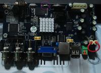
am i correct to assume that the encircled part is a 6A fuse?
diode test result to no contact.
diode test result to no contact.

Follow along with the video below to see how to install our site as a web app on your home screen.
Note: This feature may not be available in some browsers.
DO NOT try to measure continuity between IC legs, it proves nothing but could damage a good part.
am i correct to assume that the encircled part is a 6A fuse?
diode test result to no contact.

You are reading it upside down Tony! It says Y9 not 6A. The crystal beside it is marked Y4. The manufacturer is using 'Y' as the designation for quartz crystals.If it is a gapped part, it is probably a polyfuse with 6A above it. I see these a lot.
I see no c r a c k.

