Continue to Site

Welcome to EDAboard.com

Welcome to our site! EDAboard.com is an international Electronics Discussion Forum focused on EDA software, circuits, schematics, books, theory, papers, asic, pld, 8051, DSP, Network, RF, Analog Design, PCB, Service Manuals... and a whole lot more! To participate you need to register. Registration is free. Click here to register now.

Automotive Logic Probe

Status
Not open for further replies.

KitWasHere

Newbie level 3
Joined
Oct 17, 2015
Messages
3
Helped
0
Reputation
0
Reaction score
0
Trophy points
1
Activity points
47
So I'm building an automotive electrical tester and I'm running into space constraints. The device is used to probe wires to see if they are at 12v or ground, apply 12v or ground to test components (power a headlight or fan directly), and to load test a circuit. The device is powered from the vehicle's battery.

Right now I'm using an automotive relay (really big) to act as short circuit protection. Press the button and it latches the relay, and the voltage at the zener is enough to hold it closed. Power shorted to ground will make the zener circuit hiccup and turn off the relay coil. The maximum load this tester could see is around 20-30 amps. (this is a simplified circuit, all the testing stuff would be after the relay. Full schematic at the bottom of the post):
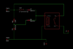
AEHmh1y.png

I'm wondering if anyone could point me in the right direction to replace this circuit with a mosfet or something of the like. Size is more important than cost for this, the relay takes up almost half of the enclosure!

Here is a full schematic in case that can help someone help me, or if someone wants to build they're own:

P7tPjhy.png

"Batt- Aux" is the negative lead for the voltmeter. The switch either connects this probe to battery ground, or leaves it floating so you can test the ground on the circuit.

This was not my idea, I just added a few features to it: https://www.instructables.com/id/Power-Logic-Probe/

Any help is really appreciated.
 
Last edited by a moderator:
Hi,

Look for protected high side switches.

Klaus
 
Make sure your input impedance is at least 10 mega ohms before you go poking random wires in newer cars. There are many very sensitive circuits - if you probe the wrong one it can set off the air bag system or check engine lights. Ive seen too many air bags pop from people using test lights and analog meters on cars. Ive even been testing wires myself with my very expensive brand name automotive meter and had door locks operate, rear defrost turn on, etc while I was searching for the wires I needed to find. Its a cool project - just be careful with the wiring on newer cars.
 
@Klaust
Thanks, I will look into those. I came across a much smaller relay that may give me enough room to use the original circuit but I will do some research on these high side switches.

@C1500
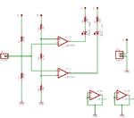
Thank you for the warning. Could you maybe point me in the right direction to adding input impedance to my project? I've found a few circuits that take care of the basic logic probe aspect while having high input impedance:

lm339LogicProbe.png

I've never used a comparator before but I will pick a few up and play with them, but this circuit still gives me an issue. It works fine for just powering the LEDs, but I would also like to have a little Voltmeter displaying a somewhat accurate reading of the same voltage triggering the lights.
Voltmeter module is similar to this: https://www.adafruit.com/products/705. From what I've found about those little displays, they have around 100k input impedance which is not much.
 

Hi,
I think - if I'm understanding your last post - similar to your probe comparator circuit, you can place an op amp before the voltmeter Vin to increase the input impedance, unless a high current input is an issue. Quite a few measurement devices have them in schematics I've seen for DMMs or oscilloscopes, etc.
Also, I imagine that with an op amp with gain you could possibly even put a large value resistor in front if you scale both to get out what goes in.
 
After a little reading, it seems you're right. A simple op amp configured as a voltage follower should give me a very high input impedance. What do you mean about high current input being an issue? In this project I plan to have a loading/voltage drop test be possible through a switch shorting the probe to ground through a 25ohm power resistor, which will draw some current. Is this bad for the opamp, or should it be okay if it's behind this loading circuit?

I have another question too. On a lot of voltmeter circuits I've come across, I'd say most don't seem to give a lot of thought to input impedance. Is there a downfall to not loading the circuit at all, or maybe a benefit to loading it somewhat that I'm not seeing? Maybe these circuits I found didn't mention impedance because it was mostly a theory lesson being taught?
 

Hi, thanks, ...technically my skill level is known as: "I don't know my (...) from my (...)", so better for some-one else to answer your doubts. Especially "What do you mean about high current input being an issue?" All I know is that the datasheet will say max. input current for the amp; and in my ignorance, if the current/signal goes to ground, not into the amp, then surely it shouldn't matter.

I'm a one trick pony, I've only made a few voltmeter type devices, the emphasis being on a few, with varying success/accuracy (one does something odd when reading the lower voltages), and depending on function (ammeter use) I haven't put an input resistor (typical 1M, I think from what I see) - I agree with you: browsing schematics it doesn't seem that necessary, but possibly actually is and I do beginner stupid mistakes, other people may save their company a production cost by omitting the resistor(s) or something, who knows... I'm not talking about voltage dividers, only input resistors.
Funny that you mentioned it, as I was thinking about this yesterday, and added a 1M to a breadboard voltmeter for yet another ammeter circuit, as it seems to make no difference to the read-out/ADC so I am going to use them from now on as I had remembered that the better articles I read explained how input impedance is important so as not to distort the circuit being measured (1 to 10Mega ohms). Perhaps the ADCs, or whatever is used, have high input impedance as the inputs are probably/basically op amps/in amp type things, which is why some designs don't (need to) include them.
At some point I'll re-read the ADC datasheets and see what they say about input impedance, might shed light on schematics that don't add any externally.
 

I think you need to do some studying d123.

Most ADC give best accuracy when fed with a low impedance source so adding a high value resistor is likely to ceate errors, especially at higher frequencies and sampling rates. The intention of a high impedance probe is to allow the voltage measurement to be taken without disturbing it. Some current flows into the probe and ADC/DVM and in circumstances where the available current is low, the extra load of the probe pulls the voltage down. The idea of an amplifer between the probe and measurement point is to place minimal load on the point being probed but reflect the voltage at lower impedance to the ADC/DVM to maintain best accuracy. Obviously an amplifier type with high input impedance is needed!

Going back to the original post, it sounds like what you are describing is like a logic probe for 12V systems, something that just tells you if 12V is present or not, maybe with a switchable load to simulate part of the automobile drawing current.

Brian.
 
  • Like
Reactions: d123

    d123

    Points: 2
    Helpful Answer Positive Rating
Status
Not open for further replies.

Part and Inventory Search

Welcome to EDABoard.com

Sponsor

Back
Top