Continue to Site

Welcome to EDAboard.com

Welcome to our site! EDAboard.com is an international Electronics Discussion Forum focused on EDA software, circuits, schematics, books, theory, papers, asic, pld, 8051, DSP, Network, RF, Analog Design, PCB, Service Manuals... and a whole lot more! To participate you need to register. Registration is free. Click here to register now.

[SOLVED] setting the output common mode - current mirror

Status
Not open for further replies.

carporsche

Junior Member level 2
Joined
Jun 8, 2009
Messages
23
Helped
4
Reputation
8
Reaction score
4
Trophy points
1,283
Activity points
1,483
Hi All

I wanted to know if anyone can give me an insight to this particular problem i have.
Basically, i have a current conveyor (single ended) and need a deterministic DC level at the output. How would i go about setting the dc- level.

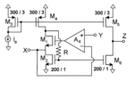
Attached is a figure. I would like to set the DC-level @ node Z


source : Carvajal, Ramón González, et al. "The flipped voltage follower: A useful cell for low-voltage low-power circuit design." Circuits and Systems I: Regular Papers, IEEE Transactions on 52.7 (2005): 1276-1291.
 

Attachments

  • ccii-fvf.png
    ccii-fvf.png
    23.2 KB · Views: 70

The thing to consider is that if you're trying to drive a load with current output it's important to have a very low resistance load. Because open circuit is the heaviest load you can use for a current output (likewise short circuit is the hardest to drive with a voltage output, that's why we leave our voltage supplies open circuit when not being used). So in general, it can be said that the load DC condition determines the DC condition of the circuit which has a current output because the output voltage shouldn't swing that much for the circuit to operate properly. Your problem can be solved by just biasing the load at the right DC level.

But I'm guessing you are asking this for simulation purposes, in that case you can put a mock control loop with ideal elements to calibrate Ib to set the output DC level, but it should only set the DC level, use extreme ideal filtering or whatever.

Disclaimer: I'm not very experienced with active filter design, someone with more experience may be more helpful.
 
You can create a replica and generate biases for M5 M6 devices. In the replica, you can set the corresponding Z node to the DC level you want using a feed back loop. So on the main circuit side, the node Z will get set to the DC voltage you expected.

In the circuit you have attached, replace M1 with a PMOS (matched to M5), and connect the output of the opamp to M5 gate. And connect the top end of the resistor to the drain of M2. Set the node Y to whatever you want the node Z to be at. Dont forget to swap the inputs of the opamp.
 
Last edited:
Thanks kemiyun, AMS012

I realized that the output DC level has to be set by the load i am driving.
For simulation purposes i set the output CM level to VDD/2

Thanks again for your suggestions
 

Status
Not open for further replies.

Part and Inventory Search

Welcome to EDABoard.com

Sponsor

Back
Top