ghoetic
Junior Member level 2
Hello everyone!
Short introduction:
Im an Automation technician with a burning desire for electronics and power electronics and pretty much everything connected with electricity.
And i have very limited electronics knowledge, but i am slowly getting a hang for things as time allows, watching countless youtube videos, reading books and searching the internet! :thumbsup:
recently there is something that has been on my mind alot, i want to design a very basic and barebone variable frequency drive. like a proof of concept build.
I understand the very basic idea behind rectifying, storing and inverting. but i also like to think that some of my ideas related to concept are far ahead of some of my practical understanding ^^.
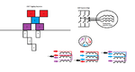
So lets get to it then! One fundamental point about the three phase system is this "There will always be a point in time when two of the phases are returning current through one" if i got that right.
And one fundamental thing about the igbt bridge is this "The two gates per phase lead (e.x 1 & 4) may never be open at the same time, this will short circuit the dc bus" much like if the igbt chopper would get damaged and stay closed.
So i started thinking and drawing symbols on paper much like the one will provide, but only just recently got a hang of "HOW I THINK" it should work or best resemble true three phase sequence. Now i have tried to search for hours something resembling this but i have had no luck. I might be dead wrong, so i will just upload this paint picture and you can tell me what you think. the boxes with number represents the pulse in time that the igbt should stay closed.
/Alexander
Short introduction:
Im an Automation technician with a burning desire for electronics and power electronics and pretty much everything connected with electricity.
And i have very limited electronics knowledge, but i am slowly getting a hang for things as time allows, watching countless youtube videos, reading books and searching the internet! :thumbsup:
recently there is something that has been on my mind alot, i want to design a very basic and barebone variable frequency drive. like a proof of concept build.
I understand the very basic idea behind rectifying, storing and inverting. but i also like to think that some of my ideas related to concept are far ahead of some of my practical understanding ^^.
So lets get to it then! One fundamental point about the three phase system is this "There will always be a point in time when two of the phases are returning current through one" if i got that right.
And one fundamental thing about the igbt bridge is this "The two gates per phase lead (e.x 1 & 4) may never be open at the same time, this will short circuit the dc bus" much like if the igbt chopper would get damaged and stay closed.
So i started thinking and drawing symbols on paper much like the one will provide, but only just recently got a hang of "HOW I THINK" it should work or best resemble true three phase sequence. Now i have tried to search for hours something resembling this but i have had no luck. I might be dead wrong, so i will just upload this paint picture and you can tell me what you think. the boxes with number represents the pulse in time that the igbt should stay closed.
/Alexander