Continue to Site

Welcome to EDAboard.com

Welcome to our site! EDAboard.com is an international Electronics Discussion Forum focused on EDA software, circuits, schematics, books, theory, papers, asic, pld, 8051, DSP, Network, RF, Analog Design, PCB, Service Manuals... and a whole lot more! To participate you need to register. Registration is free. Click here to register now.

[SOLVED] Why is this Frequency Counter not working ?

Status
Not open for further replies.
In this page

https://www.mikroe.com/chapters/view/52/chapter-4-timers/#ch4.4.2

section 4.4.2 it says one has to use T1CK pin. Should I use T1CK or T2CK pin ?

Please explain more about Time base.

A 32-bit timer module can be formed by combining a Type B and a Type C 16-bit timer module.
The Type C time base becomes the MSWord of the combined timer and the Type B time base is
the LSWord.

When configured for 32-bit operation, the control bits for the Type B time base control the operation
of the 32-bit timer. The control bits in the TxCON register for the Type C time base have no effect.
For interrupt control, the combined 32-bit timer uses the interrupt enable, interrupt flag and
interrupt priority control bits of the Type C time base. The interrupt control and status bits for the
Type B time base are not used during 32-bit timer operation.
The following configuration settings assume Timer3 is a Type C time base and Timer2 is a Type B
time base:

I think you gave info related to 32 bit Timer. I need for 32 bit counter.


Edit:

Why in this page

https://www.mikroe.com/chapters/view/52/chapter-4-timers/#ch4.4.2

section 4.4.2

T3CON is not configured ?

If I want the Timer2&3 counter to overflow at 4,29,49,67,296 should I load PR2 and PR3 with 0xFFFFFFFF ?

Is this code correct ?

Code:
void Timer23Int() org 0x22{ //Address in the interrupt vector table of timer3
  IFS0 = 0;                 // Clear interrupt request
}

void main(){
  TRISC = 0xFFFF;        //PORTC<13>=1 T2CK is input pin
  T3IF_bit = 1;
  PR2   = 0xFFFF;            //Interrupt peiod is 10 clocks
  PR3   = 0xFFFF;             //Total PR3/2=0*65536 + 10
  T2CON = 0x800A;        //Timer2/3 is synchronous counter of external pulses
  
  while(1);
}


I think
Code:
T2CON = 0x8002;

also works. Right ?
 
Last edited:

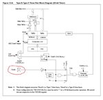
The text to which you refer indicates using the T1CK, however the image just below the text indicates using T2CK, as does the image from the dsPIC30F Family Reference Manual and dsPIC30F4013 Datasheet:

dsPIC30_32bitTimer.JPG

As does the following example code:

Code:
;   The following code example will enable Timer2 interrupts, load the 
;   Timer3:Timer2 Period register and start the 32-bit timer module 
;   consisting of Timer3 and Timer2. When a 32-bit period match occurs 
;   the timer will simply roll over and continue counting. 
;   However, when at the falling edge of the Gate signal on [COLOR="#FF0000"]T2CK[/COLOR] 
;   an interrupt is generated, if enabled. The user must clear the 
;   Timer3 interrupt status flag in the software. 

CLR     T2CON              ; Stops any 16/32-bit Timer2 operation 
CLR     T3CON              ; Stops any 16-bit Timer3 operation 
CLR     TMR3               ; Clear contents of the Timer3 register 
CLR     TMR2               ; Clear contents of the Timer2 register 
MOV     #0xFFFF, w0        ; Load the Period Register3 
MOV     w0, PR3            ; with the value 0xFFFF 
MOV     w0, PR2            ; Load the Period Register2 with value 0xFFFF
BSET    IPC1,    #T3IP0    ; Setup Timer3 interrupt for 
BCLR    IPC1,    #T3IP1    ; desired priority level
BCLR    IPC1,    #T3IP2    ; (this example assigns level 1 priority)
BCLR    IFS0,    #T3IF     ; Clear the Timer3 interrupt status flag 
BSET    IEC0,    #T3IE     ; Enable Timer3 interrupts
MOV     #0x804C, w0        ; Enable 32-bit Timer operation and 
MOV     w0, T2CON          ; Start 32-bit timer in gated time 

; accumulation mode. 
;   Example code for Timer3 ISR 

__T3Interrupt: 
BCLR    IFS0,    #T3IF     ; Reset Timer3 interrupt flag
; User code goes here.
RETFIE

If I remember correctly, if the timers are joined in 32 bit mode, the T2CK must be used. Which suggests the MikroC text is most likely a typo.

I would need to breakout the dsPICDEM 2 board to run a quick test to be certain, however I suspect you can verify it just as quick.

However, please note:

12.10.3 Asynchronous Counter Mode

Type B and Type C time bases do not support the Asynchronous External Clock mode.
Therefore, no 32-bit Asynchronous Counter mode is supported.

The 32-bit timer has the following modes:
• Two independent 16-bit timers (Timer2 and
Timer3) with all 16-bit operating modes (except
Asynchronous Counter mode
)
• Single 32-bit timer operation
• Single 32-bit synchronous counter

No Asynchronous Counter mode is supported using Type B and Type C timers, in neither 16-bit nor 32-bit timer configurations.


BigDog
 
@bigdogguru.

Ok. Thank you. Why in the code you posted T2CON and T3CON are cleared ? Where does it show configuration of T2CON and T3CON so that it is used as a 32 bit Synchronous Counter ? The mikroE page didn't tell why T3CON is not configured when using Timer2/3 as a 32 bit Synchronous Counter.

If anybody has used Timer2/3 of dsPIC30F as a 32 bit Synchronous Counter then please provide me an example code showing configuration of register and the ISR.

The dsPIC30F4013 datasheet page 67 says this.

32-bit Synchronous Counter Mode: In the 32-bit
Synchronous Counter mode, the timer increments on
the rising edge of the applied external clock signal
which is synchronized with the internal phase clocks.
The timer counts up to a match value preloaded in the
combined 32-bit period register PR3/PR2, then resets
to ‘0’ and continues.
When the timer is configured for the Synchronous
Counter mode of operation and the CPU goes into the
Idle mode, the timer will stop incrementing unless the
TSIDL (T2CON<13>) bit = 0. If TSIDL = 1, the timer
module logic will resume the incrementing sequence
upon termination of the CPU Idle mode.

Related to the info given here

https://www.mikroe.com/chapters/view/52/chapter-4-timers/#ch4.4.2

Section 4.4.2

The image tells that T2CK pin is used. So, I think it is correct because we are using Timer2 and 3. The things that are not clear are why T3CON is not configured ?

Should T3CON be equal to 0x0000 ?

In the ISR code IFS0 is cleared and it clears both T2IF and T3IF. Can we instead clear T2IF first and then T3IF in the ISR because I don't want to clear other interrupt flags of IFS0 register.

Is 0x8002 is a valid value for the T2CON ?
 
Last edited:

Why in the code you posted T2CON and T3CON are cleared ? Where does it show configuration of T2CON and T3CON so that it is used as a 32 bit Synchronous Counter ? The mikroE page didn't tell why T3CON is not configured when using Timer2/3 as a 32 bit Synchronous Counter.

Reference the previous quote from the dsPIC30F Family User Manual:

When configured for 32-bit operation, the control bits for the Type B time base control the operation
of the 32-bit timer. The control bits in the TxCON register for the Type C time base have no effect.

Timer 2 is a Type B, while Timer 3 is a Type C.

Therefore, the control bits of Timer 2 control the operation when the two timers are configured as 32-bit timer.

If anybody has used Timer2/3 of dsPIC30F as a 32 bit Synchronous Counter then please provide me an example code showing configuration of register and the ISR.

I certainly have previous code examples using either C30 or XC16 compilers, however I do not use MikroC.

The following is an example of a 32-bit Synchronous Counter in assembly language:

Example 12-6: Initialization Code for 32-bit Synchronous Counter Mode Using an External Clock Input


Code ASM - [expand]
1
2
3
4
5
6
7
8
9
10
11
12
13
14
15
16
17
18
19
20
21
22
23
24
25
;   The following code example will enable Timer2 interrupts, load 
;   the Timer3:Timer2 Period register and start the 32-bit timer 
;   module consisting of Timer3 and Timer2. 
;   When a 32-bit period match interrupt occurs, the user must clear 
;   the Timer3 interrupt status flag in the software. 
CLR     T2CON          ; Stops any 16/32-bit Timer2 operation 
CLR     T3CON          ; Stops any 16-bit Timer3 operation 
CLR     TMR3           ; Clear contents of the Timer3 timer register 
CLR     TMR2           ; Clear contents of the Timer2 timer register 
MOV     #0xFFFF, w0    ; Load the Period Register3 
MOV     w0, PR3        ; with the value 0xFFFF 
MOV     w0, PR2        ; Load the Period Register2 with value 0xFFFF
BSET    IPC1,   #T3IP0  ; Setup Timer3 interrupt for 
BCLR    IPC1,   #T3IP1  ; desired priority level
BCLR    IPC1,   #T3IP2  ; (this example assigns level 1 priority)
BCLR    IFS0,   #T3IF   ; Clear the Timer3 interrupt status flag 
BSET    IEC0,   #T3IE   ; Enable Timer3 interrupts
MOV     #0x801A, w0    ; Enable 32-bit Timer operation and start 
MOV     w0, T2CON      ; 32-bit timer with prescaler settings at 
; 1:8 and clock source set to external clock 
;   Example code for Timer3 ISR 
__T3Interrupt: 
BCLR    IFS0,   #T3IF   ; Reset Timer3 interrupt flag
; User code goes here.
RETFIE


BigDog
 
Things are clear now but I made a code and it is not working. Have a look at the .c file.

- - - Updated - - -

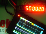
It worked but there is some problem. It displays correct value if 50 KHz is measured but displays wrong value if measured frequency is greater than 50 KHz. What is the problem ?

- - - Updated - - -

After TMR2 becomes 0xFFFF, TMR3 starts incrementing. Right ? If yes, then if TMR2 is 0xFFFF and TMR3 is 0x0001 then result should be 65536. So, I have to add TMR3 and TMR2 values ?

Edit:

Ok. I had to do this.

Code:
freq = (((double)TMR3 * 65536.0)  + (double)TMR2);

Now it is working fine.
 

Attachments

  • Frequency Counter Timer2&3 as 32 Bit Counter.rar
    77.4 KB · Views: 52
  • Frequency Counter Timer2&3 as 32 Bit Counter rev1.rar
    77.6 KB · Views: 56
  • fc 50 KHz.png
    fc 50 KHz.png
    1 MB · Views: 57

It worked but there is some problem. It displays correct value if 50 KHz is measured but displays wrong value if measured frequency is greater than 50 KHz. What is the problem ?

I still need to examine your code in more detail when I get the chance, however certainly several likely issues exist in the following statement:

freq = ((overflow * 4294967296.0) + (double)(TMR3 << 16) + TMR2);

Reference: dsPIC30F Family Reference Manual, Section: 12.11, Page: 12-21
12.11 Reading and Writing into 32-bit Timers

In order for 32-bit read/write operations to be synchronized between the LSWord and MSWord
of the 32-bit timer, additional control logic and holding registers are utilized (see Figure 12-6).
Each Type C time base has a register called TMRxHLD, that is used when reading or writing the
timer register pair. The TMRxHLD registers are only used when their respective timers are
configured for 32-bit operation.

Assuming TMR3:TMR2 form a 32-bit timer pair; the user should first read the LSWord of the timer
value from the TMR2 register. The read of the LSWord will automatically transfer the contents of
TMR3 into the TMR3HLD register. The user can then read TMR3HLD to get the MSWord of the
timer value.

As the C language standard offers no definitive statement in regards to what order the contents of variables within a single C statement are retrieved, i.e., whether the value of TMR2 SFR is retrieved before value of TMR3 SFR, in such cases, one should always copy the contents of each variable (SFR) in their intended order to a shadow variables/registers and then use the values contained in the shadow variables/registers to perform the necessary calculations.

Like so:
Code:
sTMR2 = TMR2;
sTMR3 = [COLOR="#FF0000"]TMR3HLD[/COLOR];

freq = ..... sTMR3.....sTMR2

And conversely, when writing a value to the 32-bit Timer:
To write a value to the TMR3:TMR2 register pair, the user should first write the MSWord to the
TMR3HLD register. When the LSWord of the timer value is written to TMR2, the contents of
TMR3HLD will automatically be transferred to the TMR3 register


After TMR2 becomes 0xFFFF, TMR3 starts incrementing. Right ? If yes, then if TMR2 is 0xFFFF and TMR3 is 0x0001 then result should be 65536. So, I have to add TMR3 and TMR2 values ?

Correct, but remember to read and write the value from/to shadow variables/registers in the correct order and utilize TMR3HLD, rather than TMR3, then perform the necessary calculations using the shadow variables/registers.


Ok. I had to do this.

Code:
freq = (((double)TMR3 * 65536.0)  + (double)TMR2);

Now it is working fine.

Then you're lucky and I wouldn't count on it, your are still utilizing TMR3 instead of TMR3HLD and there are no guarantee in what order the values are retrieved, i.e., a change in the compiler version could sudden create issues.


BigDog
 

What does TMR3HLD hold when TMR2 overflows ? 1 ? I mean TMR3 is copied into TMR3HLD ? How often or when the value is copied into it ?
 

What does TMR3HLD hold when TMR2 overflows ? 1 ? I mean TMR3 is copied into TMR3HLD ? How often or when the value is copied into it ?

The primary purpose of the TMR3HLD SFR can be best illustrated with an example.

Consider the following situation where the TMR3/TMR2 pair contain the value 0x0000FFFF:

Assume TMR2 (LSWord) contains the value 0xFFFF, the value in TMR2 is then copied to another variable, sTMR2, immediately after the copy the clock on T2CK increments that value of TMR2 which in turn increments TMR3 (MSWord) to 0x0001, the value in TMR3 is then copied to another variable, sTMR3. The resulting 32-bit value contained in the sTMR3/sTMR2 pair is now erroneously 0x0001FFFF, rather than the original value of 0x0000FFFF when the value of TMR2 was first read.

Now consider the same situation where the TMR3/TMR2 pair contain the value 0x0000FFFF, while using the TMR3HLD SFR:

Assume TMR2 (LSWord) contains the value 0xFFFF, the value in TMR2 is then copied to another variable, sTMR2, which immediate triggers the value contained in TMR3 (MSWord), 0x0000, to be copied to TMR3HLD, immediately after the copy the clock on T2CK increments that value in TMR2 which in turn increments TMR3 to 0x0001, TMR3HLD is now copied to another variable, sTMR3, which contains the correct MSWord, 0x0000, at the time of the copy to sTMR2 the resulting 32-bit value contained in the sTMR3/sTMR2 pair is now correct, 0x0000FFFF, in relationship to when the value of TMR2 was first read.

As the example above illustrates, the reading of the value contained in TMR2, immediately triggers the value contained in TMR3 to be copied to TMR3HLD, thus retaining the correct 32-bit value for future calculations, regardless of any further increments triggered by the clock on T2CK.


BigDog
 
Thank you. Now I have a clear understanding of using type B and C timers as 32 bit Timers/Counters.
 

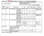
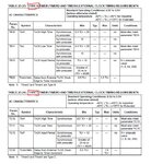
If you are curious as to how to determine the specific type of a timer, the type is typically listed in the AC Characteristic section of the datasheet for the specific dsPIC30F device.

dsPIC30TimerType1.JPG

dsPIC30FTimerType2.JPG

BigDog
 

Status
Not open for further replies.

Part and Inventory Search

Welcome to EDABoard.com

Sponsor

Back
Top