Continue to Site

Welcome to EDAboard.com

Welcome to our site! EDAboard.com is an international Electronics Discussion Forum focused on EDA software, circuits, schematics, books, theory, papers, asic, pld, 8051, DSP, Network, RF, Analog Design, PCB, Service Manuals... and a whole lot more! To participate you need to register. Registration is free. Click here to register now.

[SOLVED] Why is this Frequency Counter not working ?

Status
Not open for further replies.

pic.programmer

Advanced Member level 3
Joined
Aug 19, 2015
Messages
773
Helped
141
Reputation
284
Reaction score
140
Trophy points
43
Activity points
7,531
Why is this Frequency Counter not working ?

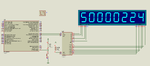
I am using dsPIC30F4013. Crystal used is 8 MHz. XT with 8x PLL is used. So, system clock is 64 MHz. I am using mikroC PRO dsPIC Compiler.

Timer2 is used to generate exact 1 sec delay. Timer1 is used as a counter and input is from T1CK pin. I am trying the design a frequency counter which can measure upto 50 MHz.

1:8 prescalar is used with Timer1 counter. So, the final result is

Code:
freq = ((overflow << 16) + TMR1) * 8;

The display code is correct because it works with PIC18F46K22. I have configured ADPCFG so that all pins are digital IO pins.

What am I missing ?

- - - Updated - - -

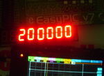
I have tested this in hardware and it doesn't display anything (not even 0) on the MAX7219 based 7 segment display. I can tell that the MAX7219 related code is fine because I have used the same code in one of my PIC18F26K22 based frequency counter and it displays data fine. So, the problem is either related to Timer1 and/or Timer2 related codes.

Have I configured the Timer1 properly. I am sure Timer2 configuration to generate 1 sec delay is correct because I have used mikroE Timer Calculator Tool.

For Timer1, PR1 is loaded with 0xFFFF. So, when Timer1 counts 0xFFFF using external clock pulses then it has to overflow and generate the Timer1 interrupt.

Edit:

I had forgotten to call these two functions after port initialization.

Code:
MAX7219init();
Display(0);

Now the display displays 0. So, display is fine. I tested the Timer2 related code in a different project and it blinks an LED at 1 Hz. So, I can tell that Timer2 related code is also correct.

All I can say is interrupts are not occuring. I think the problem is with Timer1 which is not counting the external pulses.

This is the new code. Forum is not allowing me to attach files and hence I am posting the code.


Code C - [expand]
1
2
3
4
5
6
7
8
9
10
11
12
13
14
15
16
17
18
19
20
21
22
23
24
25
26
27
28
29
30
31
32
33
34
35
36
37
38
39
40
41
42
43
44
45
46
47
48
49
50
51
52
53
54
55
56
57
58
59
60
61
62
63
64
65
66
67
68
69
70
71
72
73
74
75
76
77
78
79
80
81
82
83
84
85
86
87
88
89
90
91
92
93
94
95
96
97
98
99
100
101
102
103
104
105
106
107
108
109
110
111
112
113
114
115
116
117
118
119
120
121
122
123
124
125
126
127
128
129
130
131
132
133
134
135
136
137
138
139
140
141
142
143
144
145
146
147
148
149
150
151
152
153
154
155
156
157
158
159
160
161
162
163
164
165
166
167
168
169
170
171
172
173
sbit Data7219 at LATB0_bit;
sbit Load7219 at LATB1_bit ;
sbit Clk7219 at LATB2_bit;
 
sbit Data7219_Direction at TRISB0_bit;
sbit Load7219_Direction at TRISB1_bit;
sbit Clk7219_Direction at TRISB2_bit;
 
const unsigned char Font_B[16] = {0x7e,0x30,0x6d,0x79,0x33,0x5b,0x5f,0x70,
                                  0x7f,0x7b,0x77,0x1f,0x4e,0x3d,0x4f,0x47
};
 
void Send7219 (char,char);
void Send7219byte(char);
void MAX7219init();
void Display(unsigned long);
 
unsigned long overflow = 0;  // Count overflow from interrupt.
short send_to_UART = 0;
char str[17];
unsigned long  freq = 0;
 
//Timer2
//Prescaler 1:256; PR2 Preload = 62500; Actual Interrupt Time = 1
//Place/Copy this part in declaration section
void InitTimer2(){
    T2CON = 0x8030;
    T2IE_bit = 1;
    T2IF_bit = 0;
    IPC0 = IPC0 | 0x1000;
    PR2 = 62500;
}
 
void Timer2Interrupt() iv IVT_ADDR_T2INTERRUPT {
    T2IF_bit = 0;
    //Enter your code here
    T2CON.TON = 0;
    T1CON.TON = 0;
    //LATD0_bit = ~LATD0_bit;
    send_to_UART = 1;
}
 
 
void Timer1Interrupt() iv IVT_ADDR_T1INTERRUPT ics ICS_AUTO {
     T1IF_bit = 0;
     overflow++;
}
 
 
void start_timer_count() {
    send_to_UART = 0;
    overflow = 0;
 
    NSTDIS_bit = 1;        // Disable All interrupts.
 
    T1CON = 0x8016;
    T1IE_bit = 0;
    TMR1 = 0;
    overflow = 0;    // Clear overflow counter.
    T1IF_bit = 0;
    PR1 = 0xFFFF;
    T1IE_bit = 1;
 
    InitTimer2();
    NSTDIS_bit = 0;         // Enaable All interrupts.
}
 
void MAX7219init() {
    Data7219_Direction = 0;
    Load7219_Direction = 0;
    Clk7219_Direction = 0;
    Data7219 = 0;
    Load7219 = 0;
    Clk7219 = 0;
    Send7219(0x09, 0x00); //Decode Mode
    Send7219(0x0A, 0x05); //Brightness
    Send7219(0x0B, 0x07); //Scan limit
    Send7219(0x0C, 0x01);
    Send7219(0x0F, 0x00);
}
 
void Send7219(char Digit, char Data_) {
    Send7219byte(Digit);
    Send7219byte(Data_);
    Data7219 = 0;
    Load7219 = 1;
    Delay_us(20);
    Load7219 = 0;
}
 
void Send7219byte(char byte) {
 
    unsigned char i;
 
    for(i = 0; i < 8; i++)
    {
        if(byte & 0x80)
                Data7219 = 1;
        else
                Data7219 = 0;
 
        Clk7219 = 1;
        Delay_us(40);
        Clk7219 = 0;
 
        byte <<= 1;
    }
}
 
void Display(unsigned long val) {
 
        unsigned char dispskip;         // add 1 if "." found within string
        unsigned char i = 0;
 
        LongToStr(val, str);     //Convert float value to string
        Ltrim(str);                     //remove spaces padded to left of string
        Rtrim(str);
        dispskip = strlen(str) - 1;
 
        if(dispskip >= 8)dispskip = 7;
 
        while(i <= dispskip) {
                if((str[dispskip - i] >= 0x30) && (str[dispskip - i] <= 0x39)) {
                      Send7219(i+1, (Font_B[str[dispskip - i] - 0x30]));//0-9
                }
 
                i++;
        }
 
        i++;
 
        while(i <= 8) {
             Send7219(i, 0);
             i++;
        }
}
 
void main() {
 
     ADPCFG = 0xFFFF;
     
     TRISA = 0x0000;
     TRISB = 0x0000;
     TRISC = 0xFFFF;
     TRISD = 0x0000;
     TRISF = 0x0000;
 
     PORTA = 0x0000;
     PORTB = 0x0000;
     PORTC = 0x0000;
     PORTD = 0x0000;
     PORTF = 0x0000;
 
     LATA = 0x0000;
     LATB = 0x0000;
     LATC = 0x0000;
     LATD = 0x0000;
     LATF = 0x0000;
     
     MAX7219init();
     Display(0);
    
     start_timer_count();
 
     while(1) {
 
         if(send_to_UART) {
             freq = ((overflow << 16) + TMR1) * 8;
             Display(freq);
             start_timer_count();
         }
     }
}


Have I missed configuring any registers ?
 

Attachments

  • Frequency Counter.rar
    56 KB · Views: 69
Last edited:

I'm suspicious of your 'freq' calculation although I haven't simulated the program. Timer1 is 16-bits wide, you shift 'overflow' 16 times then add Timer1 value to it, that makes a result 32 bits wide. Then you multiply the result by 8, making the result 36 bits wide. I'm not saying you are wrong and I don't have the mikroC dsPIC compiler with me at the moment but my first guess at the problem is that 'freq' isn't big enough to hold the result.

If I'm right, the simplest solution is to make the timing window 8 times shorter and not multiply the answer by 8.

Brian.
 
Can you explain the calculations needed. I am attaching the PIC18F46K22 based frequency counter project here. I have used the same calculation method here also and also I have used 1:8 prescalar for Timer1 here also. It is giving exact values in Proteus and also hardware. If the calculations are wrong then how am I getting exact frequency values ?

I want to make a better frequency counter and hence I am trying to make it using dsPIC30F4013.

mods, The forum is not allowing me to attach the files. Please fix the forum website. I will try to attach the file later when it allow me to attach.

Edit:

I have attached the file.

I have tried both

Code:
freq = ((TMR1_counter << 16) + (TMR1H << 8) + TMR1L) * 8;

and

Code:
freq = ((TMR1_counter * 65536) + (TMR1H << 8) + TMR1L) * 8;

both are giving same result in Proteus and also hardware. In hardware I have only measured upto 8 MHz and I am getting exact 8 MHz.


I attached the wrong file. Please use rev2 file. One more thing I have compiled the code for (for 18F46K22 version) 8 MHz x 4X PLL = 32 MHz but in Proteus we have to use 8 MHz only. We should not use the 32 MHz obtained after using PLL. This is my experience with Proteus.
 

Attachments

  • PIC18F46K22 Based Frequency Counter MAX7219 rev2.rar
    112.9 KB · Views: 73
  • 50 MHz rev2.png
    50 MHz rev2.png
    35.3 KB · Views: 126
Last edited:

The dsPIC30F4013 frequency counter worked in hardware. The developement board has header pins for all port pins and also there are tack switches for all port pins. If I feed the signal to dsPIC using the header pin for RC14 pin and at then press and hold the tact switch connected to RC14/T1CK pin then it displays the frequency data on the MAX7219 based 7 segment display but the value is not precise. The PIC18F46K22 version is far better than the dsPIC version. The PIC18F46K22 version displays 8000000 Hz as exact 8000000 Hz. I will soon post the photos of the PIC18F46K22 version working in hardware.

I think the PIC clock should be more than the clock being measured. So, should use 16 MHz + 4xPLL to get 64 MHz for the PIC and then try to measure 50 MHz pulses ?

In the previous post I posted rev2 file. It uses 8 MHz crystal with 4xPLL = 32 MHz clock and 1:8 prescalar for Timer1 used as counter and it measures 50 MHz in Proteus. I have not yet tested it in hardware with 50 MHz pulses. I have tested it in hardware with upto 8 MHz pulses and it displays exact values.

I think the dsPIC version needs some tuning so that it displays precise values.
 

As I said, I do not have a copy of the dsPIC compiler with me at the moment so I can't do more than look at the code.

You can never get an exact frequency measurement when the integer result is multiplied by 8 though. Simple math says the result can only increase in steps of 8 so some readings will be OK, others will be slightly out.

What I queried is whether 'freq', which you have stored as an 'unsigned long' has enough storage space. By shifting 'overflow' 16 places to the left, you make it the most significant 16 bits of a 32-bit number. Adding TMR1 fills in the lower 16 bits so all 32 bits are used, that's fine but by multiplying the result by 8 you shift all those 32 bits another 4 bits to the left so you now need 36 bits to store 'freq'. Without the reference materials to check, I'm not sure the compiler assigns 36 bits to an unsigned long. I could be wrong but I can't check it at the moment.

Brian.
 
The compiler help file mentions like this. See image.
 

Attachments

  • types.png
    types.png
    10.8 KB · Views: 78

That might explain the problem, an 'unsigned long' is 4 bytes wide and you are trying to squeeze 36 bits into it. 4 x 8 bits = 32 bits.
Try temporarily removing the '*8' from the freq calculation, it will show wrong answers of course but see if it shows anything at all. If it does, the solution is not to multiply by 8 but to change the count period instead.

Brian.
 
If Timer1 is configured with 1:1 prescalar then Timer1 will overflow on 65536th pulse input.

If Timer1 is configured with 1:8 prescalar then Timer1 will overflow on 65536 * 8th pulse = 5,24,288th pulse.

So, when overflow variable holds 1 then

overflow *65536 = 1 * 65536 = 65536

TMR1 will be 0

So, (overflow * 65536) * 8 = (1 * 65536) * 8 = 5,24,288.

So. Is this correct ?


To measure a 50 MHz clock without using prescalars for Timer1 (counter) what should be the PIC clock frequency ? Can I use 16 MHz with 4xPLL = 64 MHz ?

Can a PIC pin like T1CKI toggle at 50 MHz ?

- - - Updated - - -
 
Last edited:

@andre_teprom

If 50 KHz is the max value then how does dsPIC measure 50 MHz ? I am not using any prescalar for Timer1. I am feeding 8 MHz to dsPIC's T1CK pin and 8000000 Hz is displayed as 8000045. It is near but not precise. How can T1CK pin toggle at 8 MHz or 50 MHz ?
 

Had you even searched this information on uC's datasheet ?
At page 188 of the following document, it is stated a maximum speed rate of 50KHz:

Sorry Andre, that's the wrong figure you were looking at. 50KHz is the maximimum frequency when Timer1 is in oscillator mode but not when counting external signals. In many cases a 32.768KHz crystal would be connected across the Timer1 oscillator pins for use as a real time clock reference but when not in oscillator mode the input pin is wired directly to the counter hardware and works independantly of the PICs own clock. The quoted minimum cycle period, parameter TA15, is 20nS (=50MHz).

pic.programmer, as you are quoting numbers, did the fix I suggested in post #7 work?

Also remember that when using the PLL, any inaccuracy in the crystal frequency is also multiplied. For best accuracy you need to use an external temperature compensated clock or trim the internal oscillator to exact frequency by adjusting the loading capacitors. A PIC isn't designed as a frequency counter, the fact it does so is due to the expertize of the designer. If you want precise "to the Hz" measurements you are better off with a dedicated hardware solution. Don't get me wrong - the PIC is excellent but is a general purpose device, when using it to measure a precise frequency you have to consider things like interupt latency, jitter and even software flow which can all make small but significant changes to your timing window.

Brian.
 

pic.programmer, as you are quoting numbers, did the fix I suggested in post #7 work?

I have not tested that. I compiled a new version in which there is no prescalar for Timer1 counter and it runs with 16 MHz crystal + 4xPLL = 64 MHz. I removed the Timer1 prescalar because I was not getting lower frequencies precisely.

I will soon test what you have said but I still have no idea how overflow << 16 was giving exact values in Proteus and also hardware.

How can I make a cheap 50 Hz square wave generator. I need this to test my frequency counter. Is there any chip which can be interfaced to PIC using I2C or SPI and programmed to generate 50 MHz square wave ?

Don't get me wrong - the PIC is excellent but is a general purpose device, when using it to measure a precise frequency you have to consider things like interupt latency, jitter and even software flow which can all make small but significant changes to your timing window.

I will check the time taken to execute each instruction in the ISR and will also check how much time is taken after 1 sec timer0 completion to stop the timer1. I will then use those small us and ns delays and do the final calculation to get the precise frequency measurement.

As of now the PIC18F46K22 / 26K22 version of frequency counter is displaying 8000000 Hz as 8000000 Hz and dsPIC version is displaying it as 8000045 Hz.

Also lower frequencies like 1 KHz is displayed as 1 KHz only.

For now, I need a 50 MHz square wave generator.

Is it better to use TCXO or OCXO oscillator ?

See attached image. It shows frequency counter displaying 100 KHz as 100 KHz in hardware. There is no fluctuation in the value.
 

Attachments

  • 100 KHz.png
    100 KHz.png
    896.5 KB · Views: 73

Even my 850,000 Rupee HP signal genertor is only accurate to about +/- 10Hz at 50MHz. Go for whichever is most affordable and available you will find both types are quite expensive.

Brian.
 

Hello


i did many test on different frequency meter (differents PIC, and asm or C langage)
the usual maxi limit for classic PIC16 18F for Timer input is about 50Mhz
OK for some PIC, bad for other..
tested successfuly at 27,125Mhz on old Radio Command ..

and over , better to use specialised divider for high frequency as MB506

tested at 60Mhz , with a quartz clock IQX02-22 (metal case 4 pins).
The main difficulty is to build an amplifier with very large band width
to adapt low level input (ie : 50mV) to square (or very near sqaure) TTL level input for Timer input.

IQX0-22C_60Mhz.jpg

details**broken link removed**
 

@betwixt

Isn't there a cheaper way to get 50 or 40 MHz ?

Is there a way to use a simple circuit with one of these crystals

https://www.taydaelectronics.com/cr...oscillators/crystal-oscillator-40-00-mhz.html

to get 40 MHz square wave ?

You get what you pay for I'm afraid. The Taydae modules are standard in the industry but their frequency may still be slightly high or low, they don't give a specification and for most uses a few hundred Hz one way or the other would make little difference. If you want absolute precision at lowest cost your best option is to lock your own oscillator to a known frequency standard. Where are you? I may be able to locate a nearby standard frequency transmission you can use as a reference. My local one for example is accurate to one cycle in several centuries!

There is another way, make your reference oscillator tunable and adjust it until a known accurate frequency gives the correct readout. For example, if your area still has analog TV, lock it to their sync pulses, they in turn will have been derived from a calibrated standard.

Brian.
 
@betwixt

I am from India.

It worked. The dsPIC30F version. The problem was with the code. I removed the TRISx, PORTx, LATx configuration and it worked properly in the development board (EasyPIC v7 for dsPIC30). I am attaching the image and also the project. You can see in image that it displays 200 KHz as 200 KHz. There is no fluctuation. Whatever frequency is measured the value is stable and precise.

The saleae capture also shows it as 200 KHz.
 

Attachments

  • dsPIC30F4013 Frequency Counter rev3.rar
    946 KB · Views: 64
  • fc 200 KHz.png
    fc 200 KHz.png
    889.4 KB · Views: 85
  • saleae capture.png
    saleae capture.png
    15.8 KB · Views: 71
Last edited:

Now I want to do some modifications for the dsPIC30F4013 frequency counter. I want to use Timer 4 and 5 to create 1 sec delay for frequency counting and use T2CK pin to count pulses. I want to use Timer2 and 3 as a 32 bit counter. The datasheet doesn't give info on configuring the registers as it gives in a PIC datasheet. Please provide info on configuring Timer 2 and 3 as a 32 bit counter.

Edit:

I have configured the T2CON and T3CON like this. Is this correct ?

Timer 2 and 3 as a 32 bit counter

Code:
T2CON = 0b1000000000000110

T3CON = 0b1000000000001010

What values should I load to PR2 and PR3 ? Should I load 0xFFFF to each ?

Will this make the Timer2&3 to overflow when 0xFFFFFFFF is reached ?

I have doubt related to the value I have used for T3CON.TCS. Is it right because there is no T3CK pin. There is only T2CK pin.

I am referring this document, section 12 Timers.

https://ww1.microchip.com/downloads/en/DeviceDoc/70059D.pdf
 
Last edited:

Please provide info on configuring Timer 2 and 3 as a 32 bit counter.

Reference: dsPIC30F Family Reference Manual, Section: 12. Timers, Page: 12-16
12.9 32-bit Timer Configuration

A 32-bit timer module can be formed by combining a Type B and a Type C 16-bit timer module.
The Type C time base becomes the MSWord of the combined timer and the Type B time base is
the LSWord.

When configured for 32-bit operation, the control bits for the Type B time base control the operation
of the 32-bit timer. The control bits in the TxCON register for the Type C time base have no effect.
For interrupt control, the combined 32-bit timer uses the interrupt enable, interrupt flag and
interrupt priority control bits of the Type C time base. The interrupt control and status bits for the
Type B time base are not used during 32-bit timer operation.
The following configuration settings assume Timer3 is a Type C time base and Timer2 is a Type B
time base:

• TON (T2CON<15>) = 1.

• T32 (T2CON<3>) = 1.

• TCKPS<1:0> (T2CON<5:4>) are used to set the Prescaler mode for Timer2 (Type B time base).

• The TMR3:TMR2 register pair contains the 32-bit value of the timer module; the TMR3
(Type C time base) register is the Most Significant Word, while the TMR2 (Type B time
base) register is the Least Significant Word of the 32-bit timer value.

• The PR3:pR2 register pair contains the 32-bit period value that is used for comparison with
the TMR3:TMR2 timer value.

• T3IE (IEC0<7>) is used to enable the 32-bit timer interrupt for this configuration.

• T3IF (IFS0<7>) is used as a status flag for the timer interrupt.

• T3IP<2:0> (IPC1<14:12>) sets the interrupt priority level for the 32-bit timer.

• T3CON<15:0> are “don’t care” bits.

Note: Refer to the device data sheet for information on the specific Type B and Type C time bases that can be combined


BigDog
 
Status
Not open for further replies.

Part and Inventory Search

Welcome to EDABoard.com

Sponsor

Back
Top