Continue to Site

Welcome to EDAboard.com

Welcome to our site! EDAboard.com is an international Electronics Discussion Forum focused on EDA software, circuits, schematics, books, theory, papers, asic, pld, 8051, DSP, Network, RF, Analog Design, PCB, Service Manuals... and a whole lot more! To participate you need to register. Registration is free. Click here to register now.

TVS uni vs bidirection in this circuit

Status
Not open for further replies.

Electro nS

Full Member level 6
Joined
Mar 9, 2013
Messages
324
Helped
49
Reputation
98
Reaction score
48
Trophy points
1,308
Activity points
3,818
Hello Guys


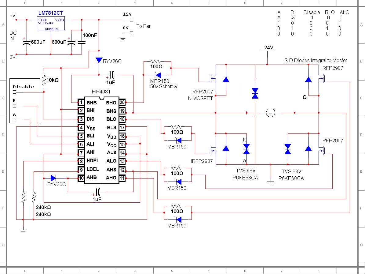
i have used this circuit (i found online last year) to drive big dc motors without much thinking but with great success


but yesterday i noticed something , there are 3 TVS (from each motor terminal to GND, and from VCC to GND) BUT THEY ARE BIDIRECTIONAL

now i am thinking , isn't it better to use Unidirectional instead in such circuit . another aspect , should i add 2 more tvs across the high side mosfets also ??

please give your opinion , maybe these diodes are not needed at all NOTE : i am using locked antiphase or sign magnitude drive methods WITH synchronous rectification

thanks and regards
 
Last edited:

Do you see a purpose of bidirectional TVS in this place? I don't.

It's also questionable, if the TVS diodes will absorb relevant energy amounts before MOSFET avalanche breakdown, but at least they don't hurt.
 

so you think like me , if they should be there , they should be unidirectional right ?

by saying their benefit is questionable , you mean the mosfet can handle and absorb the energy released by the motor ?

please explain a bit , avalanche breakdown is not something i am familar with , i choose mosfet based on Vds , Rdson and thermal calculations only

thanks for all help you provide in this forum
 

If you put an unidirectional TVS diode across low-side MOSFETs drain-source, it is going to act as a freewheeling diode (being faster than MOSFET body diode) and, depending on the freewheeling current, it might fail.

@FvM: The TVS diodes are really fast (1ps) hence they could limit the voltage across the MOSFET drain-source before the MOSFET built-in diode starts conducting. In the circuit above, the MOSFET turn-off is very fast (the gate resistor being completely shunted by the schottky diodes) thus the transient voltage across the MOSFET could be dangerous enough.
 

The TVS diodes are really fast (1ps) hence they could limit the voltage across the MOSFET drain-source before the MOSFET built-in diode starts conducting.
Really? Package inductance won't allow relevant diode current below nanosecond range. Excuse the pedantry.

If you put an unidirectional TVS diode across low-side MOSFETs drain-source, it is going to act as a freewheeling diode (being faster than MOSFET body diode) and, depending on the freewheeling current, it might fail.
Unlikely dynamic current current, but static freewheeling of a large motor might actually overload the diode (at least theorectically). In practice, both diodes will share the current according to their series resistance and area. But avoiding any forward current may be a reason to use bidrectional TVS diodes.

Assuming that every component in a given circuit has been chosen on purpose is usually unfounded.
 

Really? Package inductance won't allow relevant diode current below nanosecond range. Excuse the pedantry.

According to manufacturer website/datasheet: "fast response time: typically less than 1.0ps from 0 Volts to BV min". I've just took it for granted though.
 

NOTE : i am using locked antiphase or sign magnitude drive methods WITH synchronous rectification

thanks and regards
as i mentioned i am using Synchronous rectification . so no freewheeling in the bodydiodes

freewheeling through body didoes should happens (i think) only in the deadtime between upper and lower mosfet which is 1-1.5us in my circuit .
i donot know if in this time a dangerous voltage spike could happen , and that would the tvs take care of that .
by the way , in normal operating conditions (no emergency turn off ), a ramp function increase the duty cycle gradually , every 1ms so from zero speed to full speed it takes about 250ms , and from full speed to zero speed it takes also 250ms , in order to avoid large load dump .
if emergency button (150A switch :-D) is pressed , then the battery is disconnected and the bridge is turned off imideatly and then the mosfets and tvs or snubbers or bulk capacitors or whaterever should deal with the motor back emf

what is your opinion red alert and FVM
if you need more details i will provide
 

If you have good DC-Link capacitors (high frequency / high current / low esr polypropylene film ones), you might not need any TVS diodes at all.
 

If you have good DC-Link capacitors (high frequency / high current / low esr polypropylene film ones), you might not need any TVS diodes at all.

mmm . fine then .
i am using high frequency low esr high ripple current ELECTROLYTIC capacitors isn't this enough .
i have read before comparison between film and electrolytic where 100uF of film could replace 1000uF of electrolytic due to high ripple current , but i wasn't convinced , since all controller manufactures still use electrolytic , is there an advantage to electrolytic over film other than price and capacitance/weight ratio ??
 

I've recently used few of these PP film capacitors: BLC200J901B (20uF/900V, Irms=30A, ESR=3mO) in a full-bridge power inverter.

Some of their features, as specified on the manufacturer website:

Non-polar dielectric
Dry, resin filled
High reliability and life expectancy
Replacement for aluminum electrolytic capacitors
Lower capacitance, higher current
High ripple current
Low ESR
Low Inductance

Of course, there are good DC-Link electrolytic capacitors but the trend is to be replaced with PP film ones.
 

uni-directional devices will work fine for Fsw up to 50kHz say - just put them in the right way round...
 
I've recently used few of these PP film capacitors: BLC200J901B (20uF/900V, Irms=30A, ESR=3mO) in a full-bridge power inverter.

Some of their features, as specified on the manufacturer website:

Non-polar dielectric
Dry, resin filled
High reliability and life expectancy
Replacement for aluminum electrolytic capacitors
Lower capacitance, higher current
High ripple current
Low ESR
Low Inductance

Of course, there are good DC-Link electrolytic capacitors but the trend is to be replaced with PP film ones.

if you look at this link :https://www.electronicproducts.com/...s_in_switch_mode_power_supply_capacitors.aspx

they say that ceramic are better than film capacitors in such applications , what do think ??
what about (Capacitance and current)/size vs PP FILM
example : RCEC72A225K3DBH03A
 
Last edited:

If you have multiple low ESR electrolytic capacitors in a low inductance layout, you don't necessarily need additional bus capacitors. I presume you checked the ripple current rating.

If electrolytic capacitors are not sufficient in terms of current rating, ESR and ESL, I would primarly think about ceramic capcitors in case of a 24 V DC bus. Also high capacitance high voltage ceramic capacitors are available now, e.g. Epcos/TDK Ceralink series.
 
If you have multiple low ESR electrolytic capacitors in a low inductance layout, you don't necessarily need additional bus capacitors. I presume you checked the ripple current rating.


Yes i have studdied the ripple current current rating , and found that PolyP film capacitors have higher current rating vs electrolytic , so i might use a combination of use , regarding low inductance layout the VCC is on top layer , GND on buttom and mosfets and capacitors are almost touching something like this :

If electrolytic capacitors are not sufficient in terms of current rating, ESR and ESL, I would primarly think about ceramic capcitors in case of a 24 V DC bus. Also high capacitance high voltage ceramic capacitors are available now, e.g. Epcos/TDK Ceralink series.
please i am here to learn can you specify what you woould primary think about ceramic in this case instead of FILM , what is your choice built on ?

thanks and regards
 

Low voltage ceramic caps are considerably smaller and have lower ESR and ESL.

Take care of the capacitance versus voltage curve, use at least 35V, better 50V X5R or X7R capacitors for 24V bus.
 

Status
Not open for further replies.

Part and Inventory Search

Welcome to EDABoard.com

Sponsor

Back
Top