Continue to Site

Welcome to EDAboard.com

Welcome to our site! EDAboard.com is an international Electronics Discussion Forum focused on EDA software, circuits, schematics, books, theory, papers, asic, pld, 8051, DSP, Network, RF, Analog Design, PCB, Service Manuals... and a whole lot more! To participate you need to register. Registration is free. Click here to register now.

IR2110 - High Frequency Mosfet Switch - Simulation on LTspice

Status
Not open for further replies.

Sadek

Junior Member level 3
Joined
May 19, 2015
Messages
31
Helped
1
Reputation
2
Reaction score
0
Trophy points
6
Activity points
254
Hello,

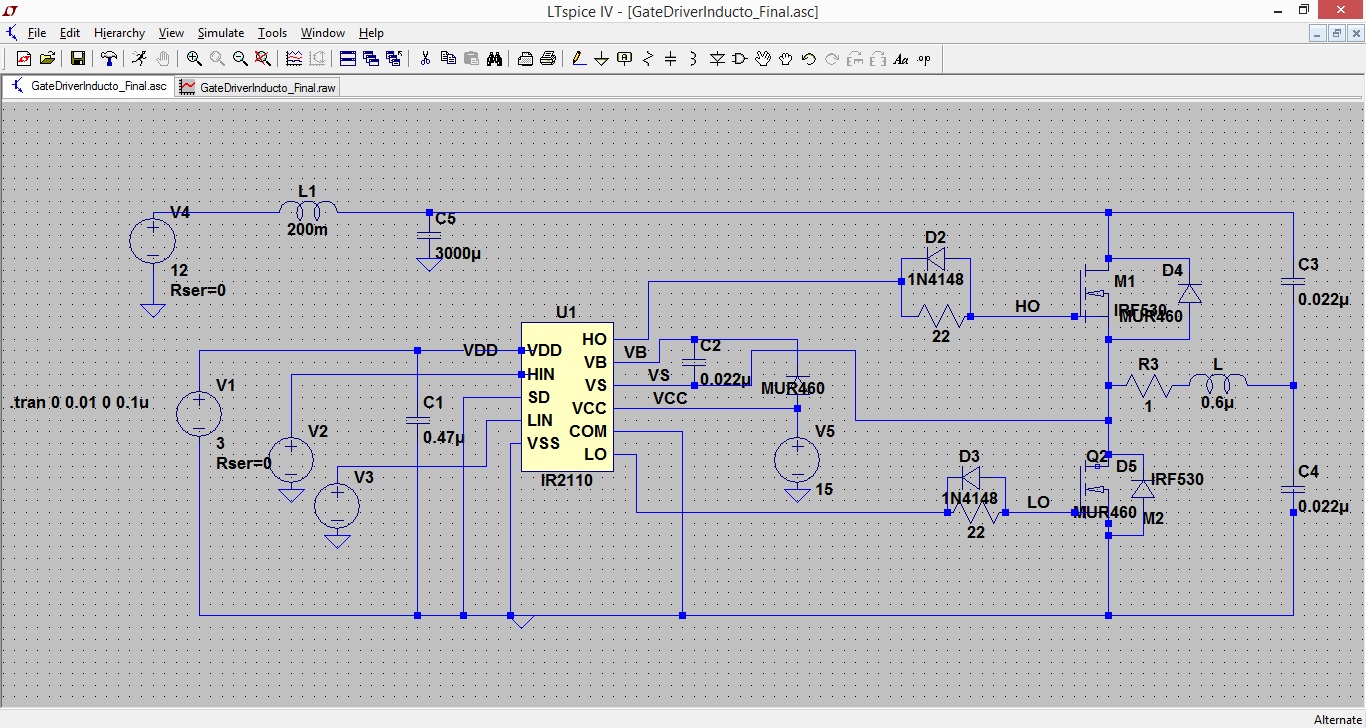
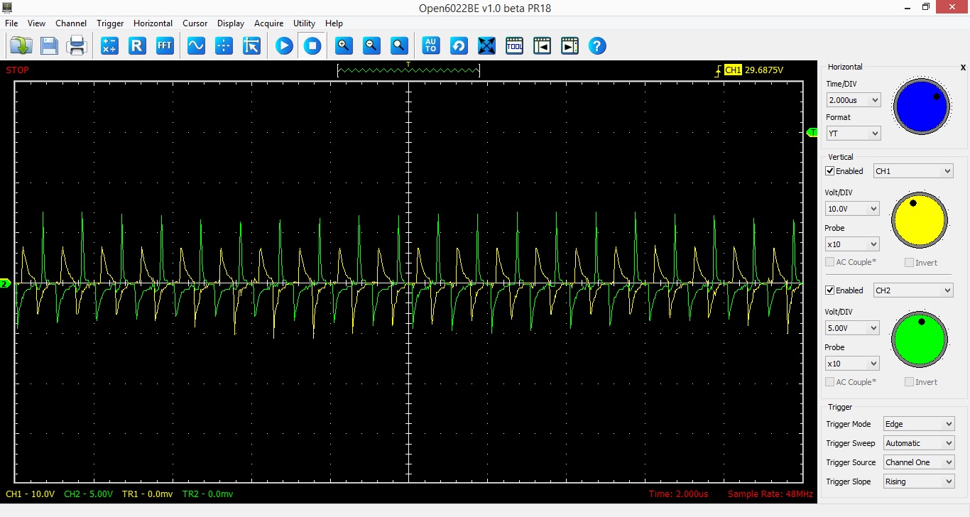
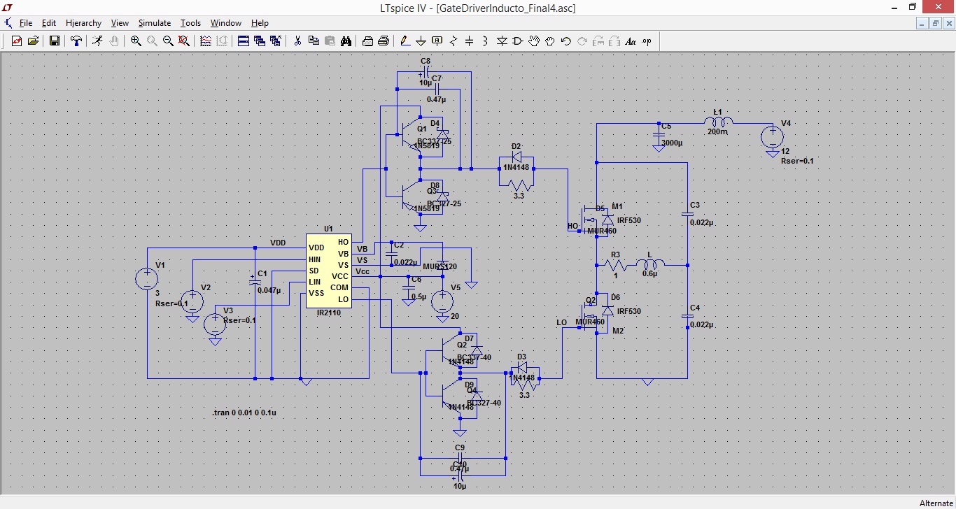
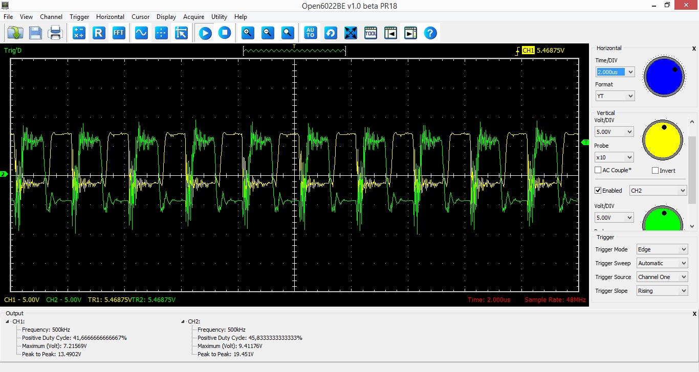
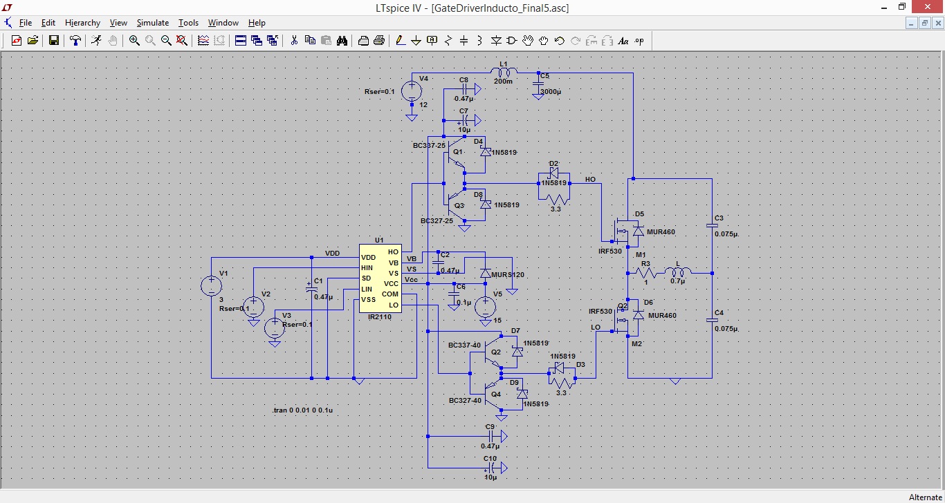
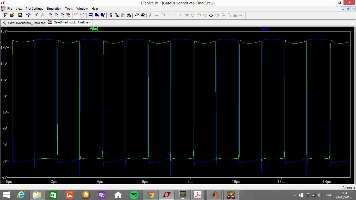
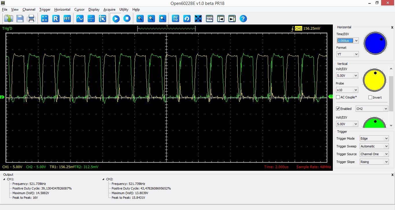
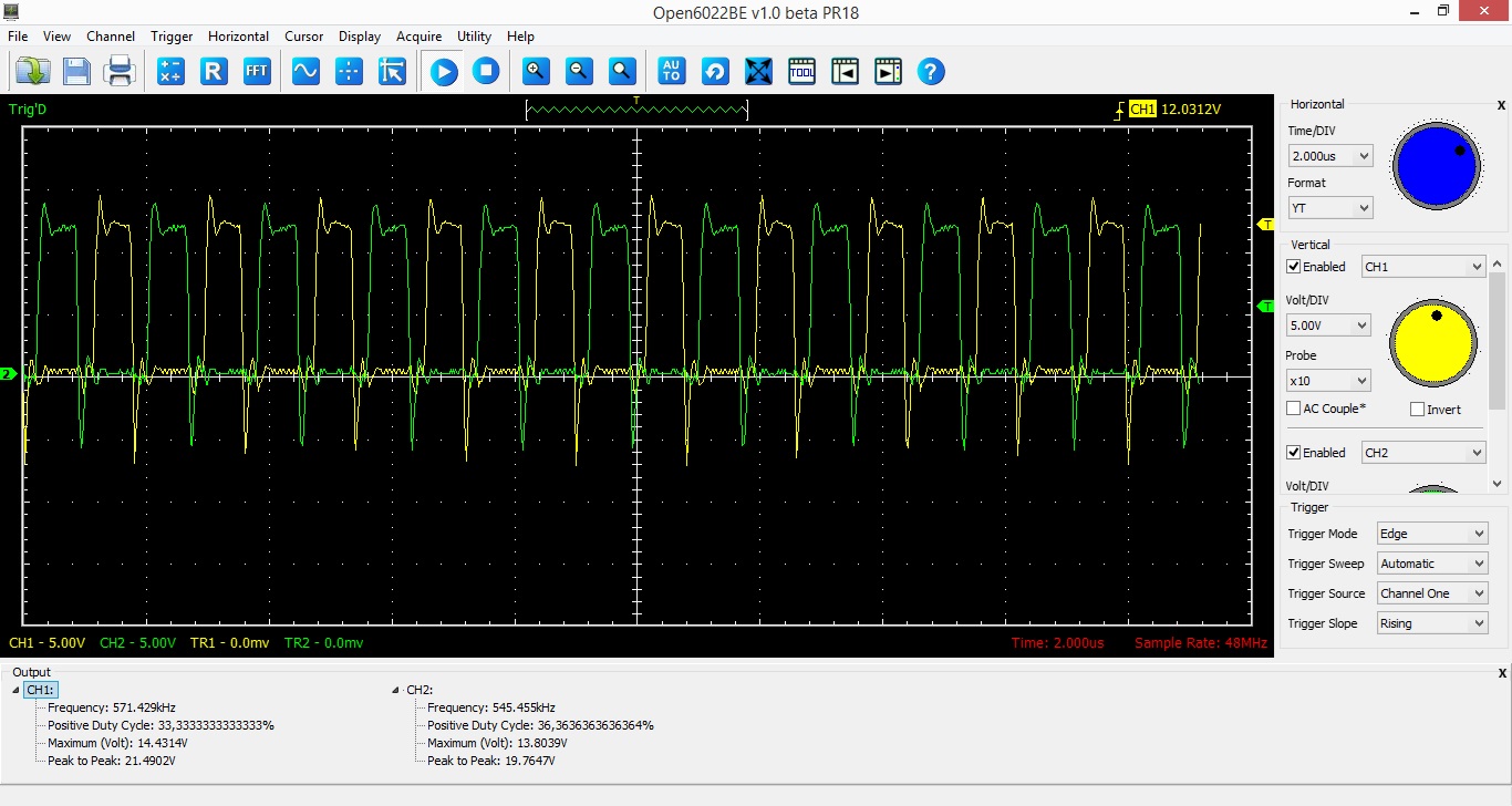
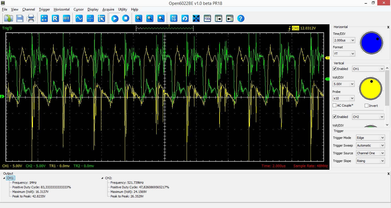
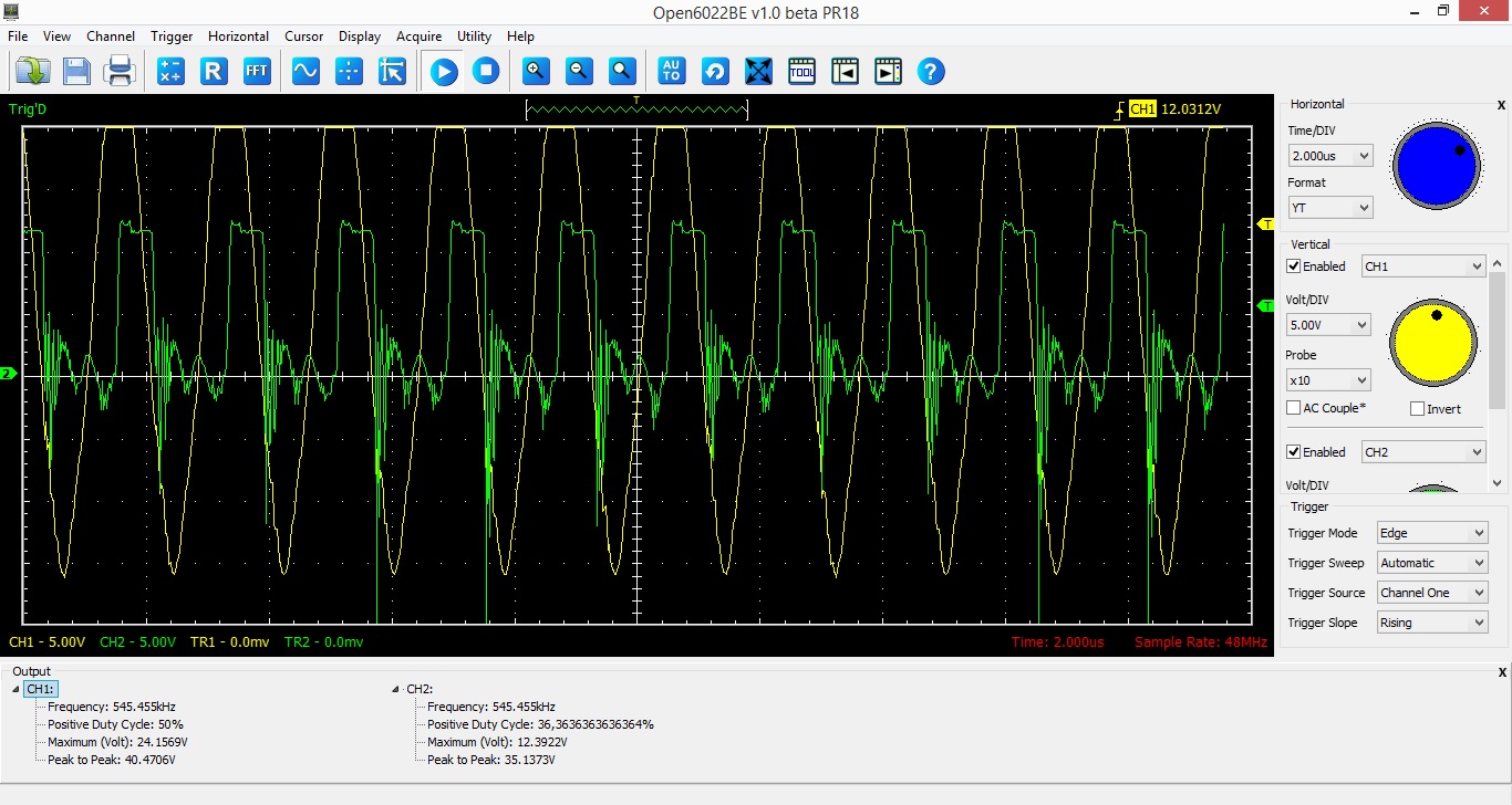
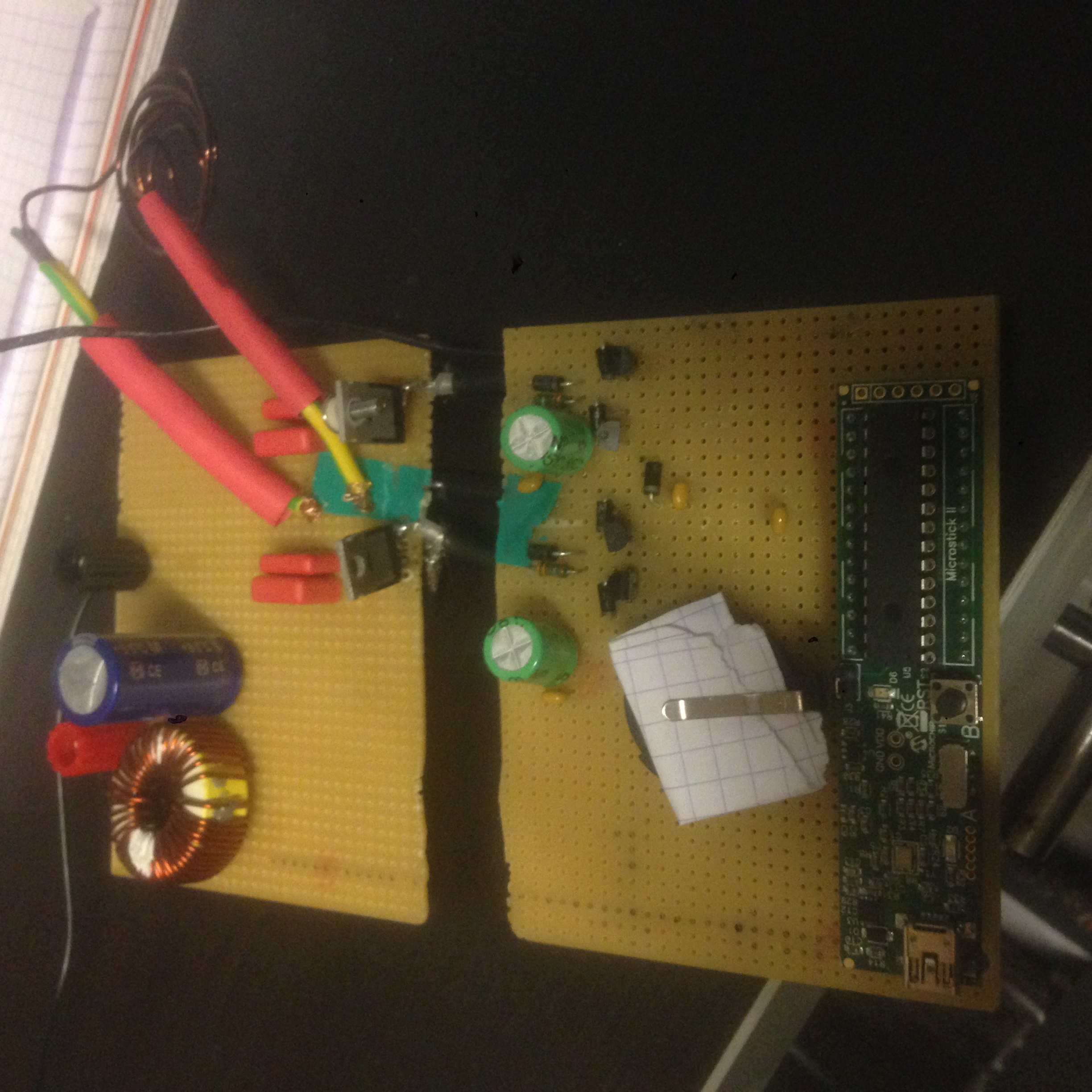
I am simulating a mosfet gate driver (IR2110), at high frequency (1MHz), for an half bridge, feeding an induction load.
My design is based on an IRF application note (AN 978).

The issues that I have are as follow:
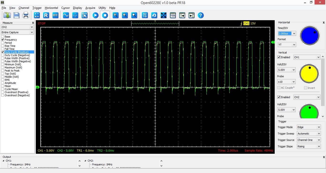
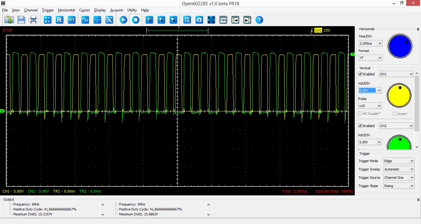
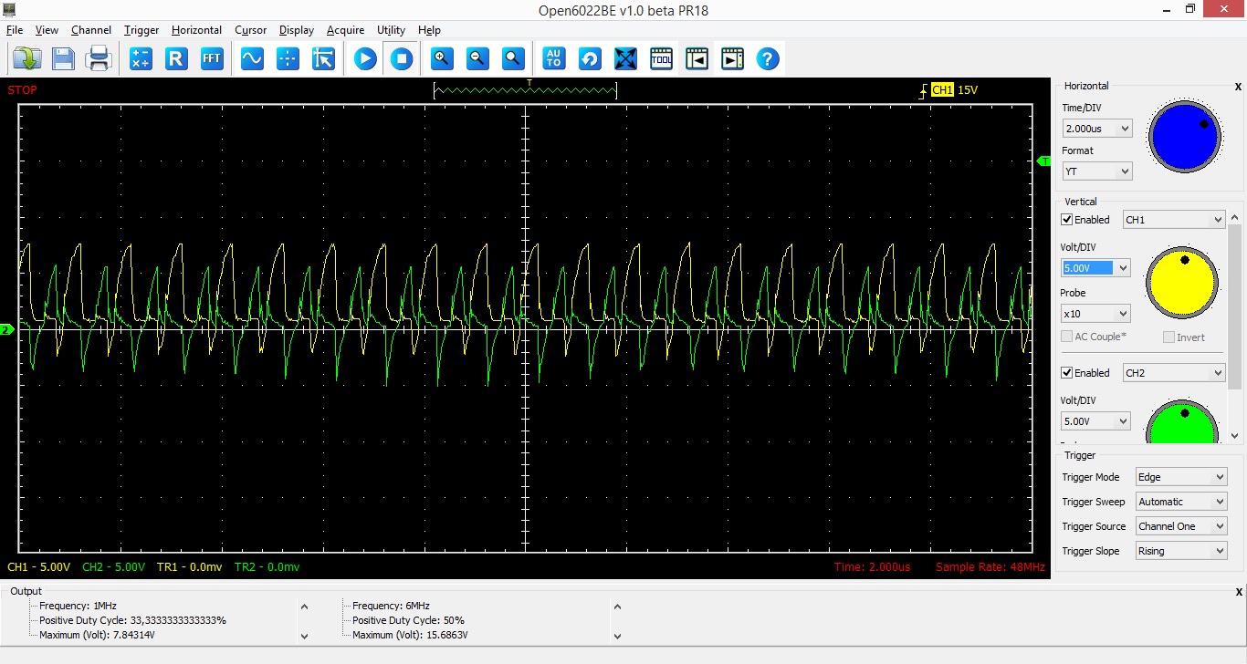
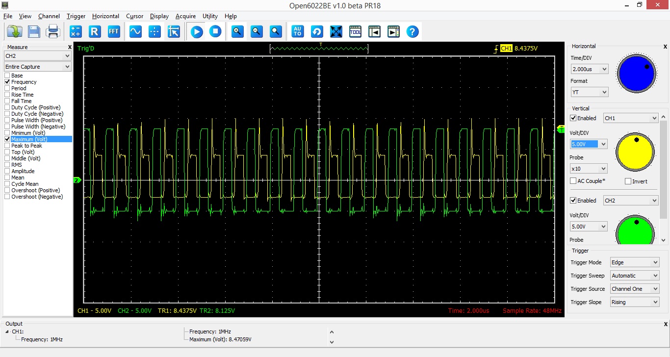
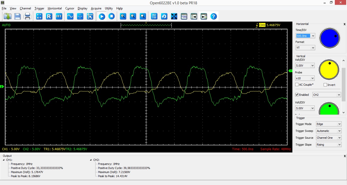
_ HO and LO values are not equal;
_ at initialization, the IR2110 introduces a delay on the first pulse. But the frequency is followed after the first pulse.

The design can be surely be improved and the configuration optimized (bootstrap capacitor value etc...). I would greatly appreciate a help !

Thanks a lot

RawValue.jpgSchematic.jpg

Sadek
 

It's likely the circuit has not reached steady state yet. Your bootstrap capacitor C2 is 0.47F, which will take a long time to charge through D1. That's probably why the high side driver is not working properly.
 

The simulation is now working fine. I had to reduce the boostrap capacitance to 0.022µF and LTspice provides me with satisfying results.

Concerning the fact that the IR2110 does not work at 1MHz, the AN978 from IRF mentions that their circuits works at 500kHz (without noticeable heating). I found some project using it 700kHz. For the moment, I haven't read anything explaining that it couldn't be used at that frequency. My idea is to use at the maximum switching frequency.

I have built the circuitry but i have troubleshoot making it work. The HO and LO are based on LIN. Even if i disconnect the HIN, the driver outputs HO and LO in phase with LIN. Which makes me think that there is something somewhere ?!
HAs anyone encount such issue with the IR2110, HO and LO based on LIN only ?

You can find a screenshot of the circuit and the oscilloscope.

I tried at different frequency (down to 10kHz) and modify the circuit but the result is the same :(

Anyone.. an idea ?!


<a title="Inducto.jpg" href="http://obrazki.elektroda.pl/6909515400_1436381294.jpg"><img src="http://obrazki.elektroda.pl/6909515400_1436381294_thumb.jpg" alt="Inducto.jpg" /></a><a title="Inducto_Oscillo.jpg" href="http://obrazki.elektroda.pl/4652448700_1436381295.jpg"><img src="http://obrazki.elektroda.pl/4652448700_1436381295_thumb.jpg" alt="Inducto_Oscillo.jpg" /></a>
 

22 ohm gate on your mosfet will give delays that are a fair percentage of the fet on time (and off time) the back diode will give a longer off time. The IR2110 might just scrape in thermally at 12V for the HVDC, but I have never seen a successful implementation above about 70kHz for HVDC > 100V, you will need to buffer the outputs if you are to stand a chance of it surviving thermally at > 100kHz...
 
HVDC will be quite limited (12 to 24V) so my hope is that the gate driver will not overheat. I disconnected the load and put Vs on ground. And now HO and LO are in phase at 15V...


But when i reconnect HO and LO to the mosfet, this is what I get. And then turn the power on.


I imagine that this is due to dud piece (one of the mosfet) or a ground issue... Anyone has any idea ?
 

you've got no buffers (gate drive IC or totem pole pairs) so the rate of rise of the gate is limited by your 22 ohm and Cin of the gate, so 1st graph could be realistic, 2nd graph is? later on? Any loop area in your gate drive connections will be deleterious also... try with just a 2n2 load (& 4k7) and see what you get....(i.e. dummy gate loads)
 
Okay for the dummy gate loads, I will try !

But I don't get why you say that i do not use any bufffer... the IR2110 is a gate drive IC. Should I add something ?

The 2nd graph is when i connect the driver ouputs to the fets, and the 3rd one whan i turn the HVDC on.

What do you mean by loop area ? What could that be ?

thanks !
 

I tried the dummy gate loads with 33pf


The result is similar to what i get when i connect HO and LO to the fet. What do you think is happening ?

- - - Updated - - -

The following graph is with a 22nf capacitor


The ringing on the 2nd graph above shows me the loop area of the wires dring the dummy load is larger than it should be, use twisted wires or coax from the lo-Z gate drive to the fets (or dummy load) even 4 square cm of loop area is detrimental for high speed gate drive...

- - - Updated - - -

But I don't get why you say that i do not use any bufffer... the IR2110 is a gate drive IC. Should I add something ?
The 2110 is not that flash at driving high freq's with lo-Z, even a BC337 / BC327 totem pole emitter follower pair on each output would improve things a lot (put schottky's across each C-E) and it will isolate the 2110 for VHF effects which is always useful, don't forget to add 470nF MLCC and 10uF electro across each buffer for supply de-coupling... a 3.3ohm res from the emitters to the fet gate should be a good starting point...
 
Thanks a lot for the inputs Orson.

I modified the circuit according to this sketch. And i used coax cable to connect to the gates.


I measured the signal directly on the fet gates for two frequencies 500kHz and 1 mHz.
For 500kHz, the signal is more stable and on for the entire period. For 1 mHz, the signal doesn't stay on for too long a,d there is more noise, especially when the power in turned on.

For the moment, even at 500kHz, the fet does not turn on. I guess this is due to the low voltage. But for both case, the signal drops under 0V, which reduces the max value even if the peak to peak value remains still (around 13V).
Do you have any idea what's happenning ? What could i modify to finally have the circuit working properly.

By the way, I realized that a switching frequency of 500kHz will be a good start...


C7, C8, C9 C10 are in the wrong place on the schematic, they should go from Vcc to 0v.. across each totem pole...

- - - Updated - - -

D2, D3 should be 40V 1A schottky,

- - - Updated - - -

Really 500kHz is all you can expect from the standard IR2110, I'm surprised its going this well...

- - - Updated - - -

Q4 & Q3 are upside down, emitters need to go together.... collectors to the supply lines...
 
Last edited:
Thanks Orson !

The simulation is working fine according to your inputs. I will try the circuitry. Hope I made no mistake this time.


Here's the sim results !

HO and LO are being driven at 500kHz. You can see that the current in the inductor is oscillating.
I am on the circuits now. I will you keep guys updated on the experimental results.


Very good, keep the layout tight and short with film caps (V short leads) on the DC rail close to the fets, hopefully your real world circuit will perform near to what you want...!
 

    Orson Cart

    Points: 2
    Helpful Answer Positive Rating

    Sadek

    Points: 2
    Helpful Answer Positive Rating
    V

    Points: 2
    Helpful Answer Positive Rating
Hello guys !

here's the experimental results.
For the moment, I have tried two different setup:
_ A: gate drive circuitry on a breadboard connected to the fets using a coax
_ B: Gate drive on same circuit with fets but still connected with a coax.

With the setup A, I was actually quite happy with the results !
Here's some screen capture of the oscilloscope.


The sine curve of the tension was a bit noisy and the high drive mosfet tended to get hot.

So, I moved the whole circuitry to the same board.


The signals are even more noisy. So the high side transistor and mosfet tended to get quite hot. I was quite happy with the resonant tank. I was surprised that the signal on the breadboard would be more stable than welding the components to the board.
This is the circuitry:


Any comments to improve the results ? How should I connect the components ?
I am using it to heat small disk of metal.

Anyway, thanks to everyone for helping getting there !
 

Well, as long as its working...! do you heatsink the fets?

- - - Updated - - -

Are you using an IR2110? for gate drive? no wonder it is hot at 545kHz...!
 
Yes, I used heatsinks for the fets.

Actually, i use an IR2110, but you can't see it on the picture. It didn't noticeably heat (as advised by IRF application note). The issue was more the high side mosfet heating, mostly due to losses, and the high side transistor (BC337).

But yeah it worked !
 

Status
Not open for further replies.

Part and Inventory Search

Welcome to EDABoard.com

Sponsor

Back
Top