Continue to Site

Welcome to EDAboard.com

Welcome to our site! EDAboard.com is an international Electronics Discussion Forum focused on EDA software, circuits, schematics, books, theory, papers, asic, pld, 8051, DSP, Network, RF, Analog Design, PCB, Service Manuals... and a whole lot more! To participate you need to register. Registration is free. Click here to register now.

Totally unsuitable wire used for SMPS transformer (skin depth)?

Status
Not open for further replies.
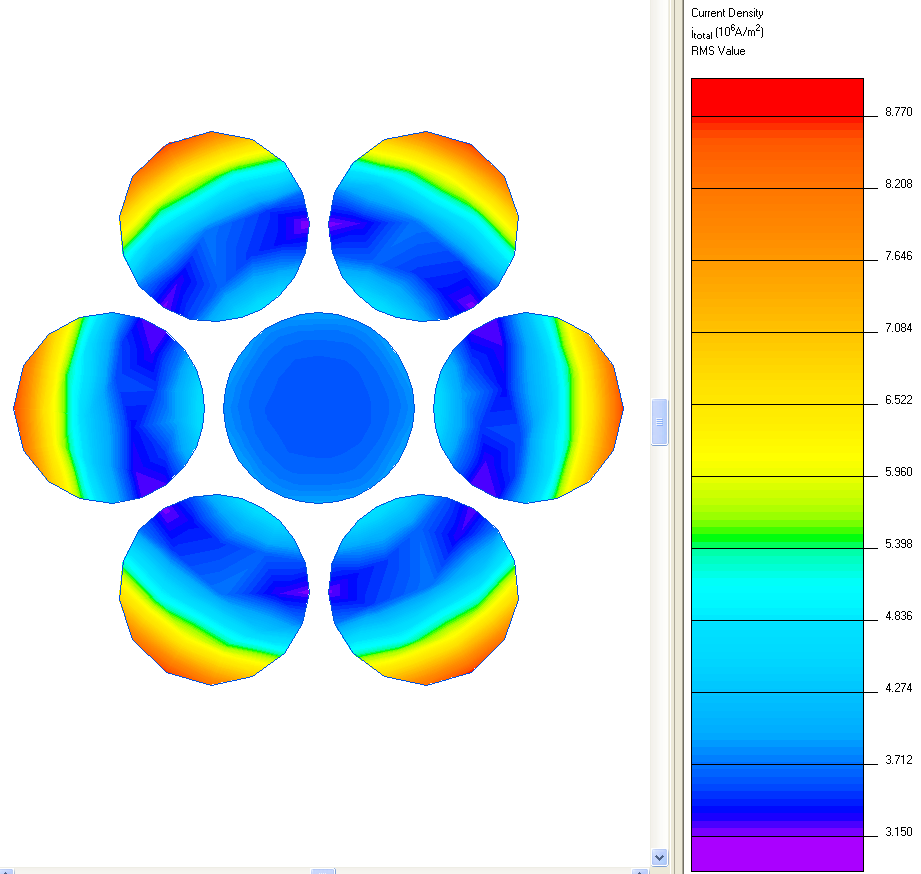
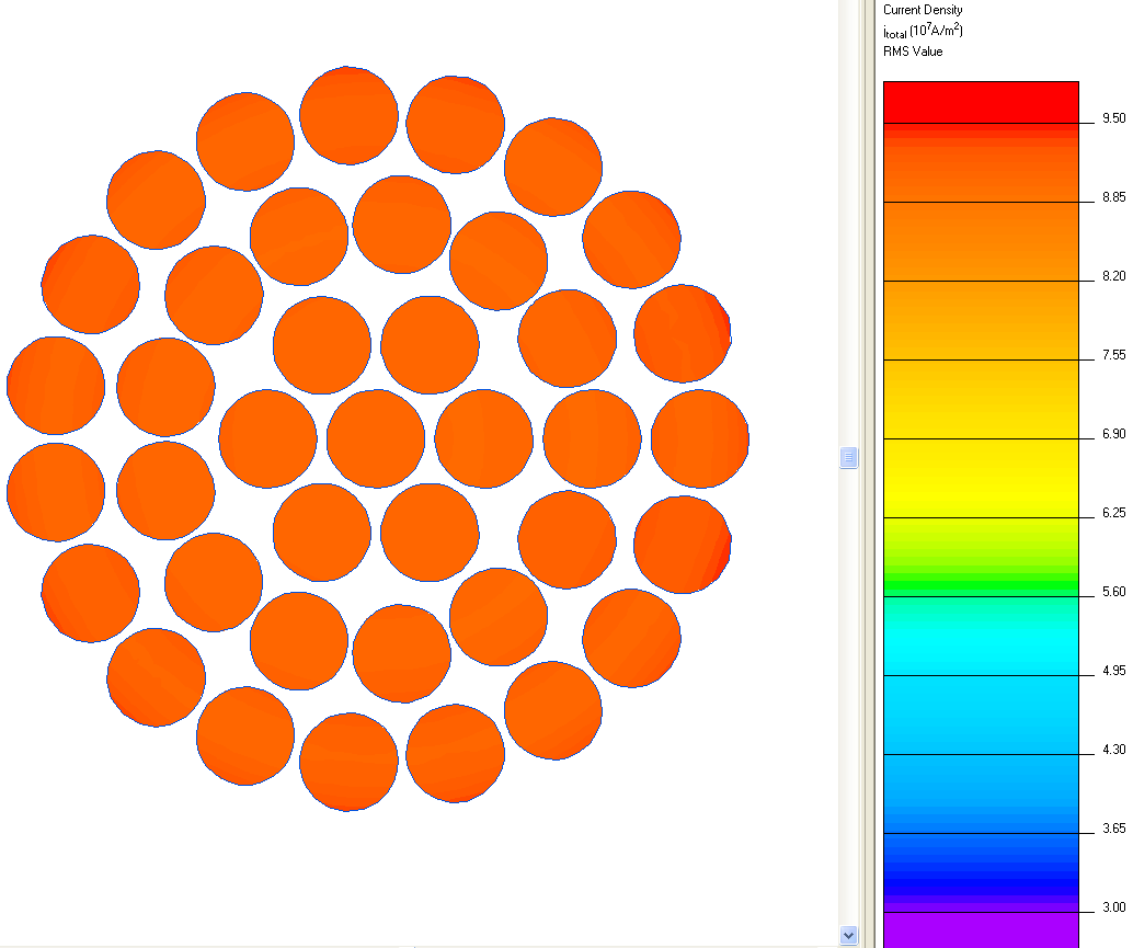
The initial issue arose to ask if the wire size of that design is appropriate or not, and the discussion came to the losses generated by the AC component subjected to the skin effect. However, the losses generated by DC component also should be considered to resize the wire, once there will have some increase on wire temperature due to this component.
 
  • Like
Reactions: treez

    T

    Points: 2
    Helpful Answer Positive Rating
Since there are times when the current is zero, there is no net average continuous DC flowing, only a mathematical DC component, DC I^2R losses apply only to steady state DC, you have to find the rms value of the trapezoids and use this to evaluate losses...the ac resistance at the fundamental freq is (close enough to) the resistance of the wire for this purpose.
 
Since there are times when the current is zero, there is no net average continuous DC flowing, only a mathematical DC component, DC I^2R losses apply only to steady state DC, you have to find the rms value of the trapezoids and use this to evaluate losses...the ac resistance at the fundamental freq is (close enough to) the resistance of the wire for this purpose.

I'm a bit surprised to hear this explanation from a profound power electronics expert.

You can't determine the total (AC + DC) losses in time domain, e.g. by calculating the RMS value of trapezoid currents because the resistance is frequency dependant. As previously mentioned, you calculate the RMS values of harmonic components, I(fn)²*Rac(fn) and sum it over all relevant frequencies. Ivag²*Rdc represents the zeroth harmonic component and must be included in the sum. I understand that andre_teprom is referring to this DC component.
 
  • Like
Reactions: treez

    T

    Points: 2
    Helpful Answer Positive Rating
And the point is, that fortunately "Ivag²*Rdc " does not suffer under the skin effect.
I think we all understand, its just that perhaps I did not explain myself properly, people think that I said that the DC level could be subtracted from the total AC value to give the current, but this was not what I was saying.

Anyhow, the crux of the matter is that in the first post, , 30x0.1mm wire has been used , and is massive overkill. As the powerint.com "PI Expert" software shows, you only need a couple of strands of ECW for a flyback smps transformer, and 30 x 0.1mm would be vastly overdoing it, and very expensive, since litz type wires like that have to be custom made.
-can you imagine some poor soul having to get 30 reels of 0.1mm and twist them together........the labour cost?....and all for the sake of winding a flyback smps transformer......its surely crazy

(the secondary uses 90 x 0.1mm wire !!!!!!!!!!!.....can you imagine it !!!)
 

Treez.

If you are uncertain about your assumptions , do some research or ask.
Keep in mind 0.1mm wire is approx AWG38.

Headphone wires routinely use braided wire 44 to 48 AWG for flexibility.

Litz or Litzendraht ( stranded de.) wire is readily available up to AWG 52.

The mass production Litz wire and bobbin wound cores is done by machines.

Any net AWG size can be chosen for a range of frequencies using the required strand size.

An expert software program does not necessarily know every topology of flyback regulator and for quasi-resonance.
 
  • Like
Reactions: treez

    T

    Points: 2
    Helpful Answer Positive Rating
treez, your latest post seems to ignore all facts that have been contributed to this thread before.

As said, 0.1 mm strand gauge is pretty standard and available from the stock at a number of suppliers. The litz wire is machine made, no "poor souls" involved.

As also reported, 0.1 mm strand is suggested for the 50 - 100 kHz frequency range in manufacturer catalogs. Applying a trade-off between AC resistance increase and minimal number of strands, strand diameters up to 0.25 or 0.3 mm may me used.

Instead of keeping on harping about "not all current is AC" you should probably calculate the RMS numbers for your specific current waveforms. In a flyback application, total AC rms is often larger than average DC.
 
  • Like
Reactions: treez

    T

    Points: 2
    Helpful Answer Positive Rating
The litz wire is machine made, no "poor souls" involved.
Agreed, but its not available generally off-the-shelf, you have to ask someone to make some for you (with the machines), when you want it.
Whereas 0.315mm ECW is off the shelf, so just doing a DIY with multiple strands of that is surely the way forward for sub 60w offline flybacks?.
 

surely not if the ESL is too high. Your experience tells you about some wrong assumptions already.

**broken link removed**
 
  • Like
Reactions: treez

    T

    Points: 2
    Helpful Answer Positive Rating
You can't determine the total (AC + DC) losses in time domain, e.g. by calculating the RMS value of trapezoid currents because the resistance is frequency dependant. As previously mentioned, you calculate the RMS values of harmonic components, I(fn)²*Rac(fn) and sum it over all relevant frequencies. Ivag²*Rdc represents the zeroth harmonic component and must be included in the sum. I understand that andre_teprom is referring to this DC component.

Actually the true rms of the current (^2) x the wire Ac res at the fundamental will get you closer than 3% to the correct losses. Different when you actually have true DC + AC in the wire...e.g. a boost choke or o/p choke...


Yes looking at the ST doc in your 1st post, they do ask for 30//0.1mm etc, very necessary to keep the losses down!

try it with thicker wire and see the extra heat for yourself...!
 
Last edited:
Yes looking at the ST doc in your 1st post, they do ask for 30//0.1mm etc, very necessary to keep the losses down!
I've seen plenty of 40-65w flybacks that use just a couple of strands of 0.315mm ECW and the losses are well OK.
If you do a 65W flyback design on powerint.com "PI Expert" software, you certainly don't get 30 x 0.1mm wire being used...........I know its software, but that software is used to design an enormous percentage of the flybacks in use in the world today, such is the ubiquity of powering.com flyback IC's.

That 30 x 0.1mm wire will have to be machine made for you when you need it, that means someone has to go into a warehouse, dig out 30 reels of 0.1mm wire, and hook them all up to a litz machine, and make the stuff for you...that will be expensive..............if you use just a few strands of 0.315mm or 0.5mm wire, then you can just wind the strands direct to the former.
 

That 30 x 0.1mm wire will have to be machine made for you when you need it, that means someone has to go into a warehouse, dig out 30 reels of 0.1mm wire, and hook them all up to a litz machine, and make the stuff for you...that will be expensive..............if you use just a few strands of 0.315mm or 0.5mm wire, then you can just wind the strands direct to the former.

I already commented the "custom-made" rubbish before. In Germany, you can get small litz wire prototyping reels from a number of distributors, I remember to have seen similar offers from UK and US vendors.


The problem with self elaborated litz wire is that the wires actually have to be stranded, not just layed parallel. For the skin depth calculation, you should assume an asymmetrical current distribution, means that the strand diameter must be considerably below skin depth to avoid skin and proximity effect losses.

- - - Updated - - -

See the current density plot of a seven x 0.5 mm strand at 85 kHz. modelled with Quickfield Student. The wires are setup for series connection, according to a perfect strand where the innner and outer wires change periodically. Otherwise the inner wire would get a lower current share.

The integral calculator shows an AC resistance about 60% above DC value.

 
Thanks FvM, that’s very interesting to hear of off-the-shelf 30x0.1mm wire (CLI200/30).

It is frustrating that they have not included the diameter of this 30x0.1mm wire, including upper tolerance diameter, as this is essential info when one is winding a transformer, as you know.
The price is interesting, £24 for 69 metres, whereas a spool of plain , 0.55mm enamelled copper wire, (which has the same area as 30x0.1mm), costs some £16 for 1430 metres, so the stranded stuff is more than 30 times as expensive.

When I think of a piece of 30x0.1mm wire, it seems to me that all those 0.1mm strands are couped up tightly together, and surely the proximity effect for them would be particularly bad.

..just seen your above edit and diagram...wow, the inner wire is carrying much less than all the outers.
 

No doubt that litz wire is more expensive than solid enamelled wire. The pricing of prototyping reels is nevertheless different from production quantities, so compare them with care.

There will be little proximity effect in a fine stranded litz wire. That's one reason why 0.1 mm strands are sugested for the 50 to 100 kHz range.

See the 0.1 mm strand current distribution, colour scale is set similar to 0.5 mm plot for better comparison.

 
  • Like
Reactions: treez

    T

    Points: 2
    Helpful Answer Positive Rating
Treez,As my expensive in China factory, we often use such 0.1mm*30P or 0.1mm*90P litz wire. the cost isn't too expensive like you image.
 
  • Like
Reactions: treez

    T

    Points: 2
    Helpful Answer Positive Rating
According to this MATLAB model of skin effect with original 85KHz applied at a wire 0,1mm diameter as mentioned at post #1, seems like the initial treez assumption could be correct, due current distributions at whole conductor is likely to be the same :

CurrentDensity.JPG

Once this is not a tool especially designed to deal with electromagnetic fields like the above presented by FvM, I´m in doubt if the result is correct.
 

Attachments

  • Skin.zip
    2.8 KB · Views: 57
  • Like
Reactions: treez

    T

    Points: 2
    Helpful Answer Positive Rating
I´m in doubt if the result is correct
Looks basically correct, the variation is too small to verify it with the FEM results. Did you plot the current density for 0.5 mm wire? Also with more than one wire, proximity effect can cause an asymmetrical current distribution.

- - - Updated - - -

Running the Matlab program for 0.5 mm wire diameter gives similar current distributions as Quickfield for a single wire, but not exactly (7 versus 9 % current density variation). I must confess that I don't know which is right. Most of the 60 % resistance increase is however generated by proximity effect related asymmetries. Looking only at a single wire (basic skin effect) underestimates the problem.
 
  • Like
Reactions: treez

    T

    Points: 2
    Helpful Answer Positive Rating
The diameter parameter is 0,1mm, so that the picture shows the shape across a section from -0,05mm to +0,05mm bounds.

In fact, the model do not deals with multiple wires, and you are correct; the final effect of a multi strand wire cord is almost the same as a thicker single wire, the current distribution tends to migrate towards the periphery of the bunch.
 
  • Like
Reactions: treez

    T

    Points: 2
    Helpful Answer Positive Rating
the final effect of a multi strand wire cord is almost the same as a thicker single wire, the current distribution tends to migrate towards the periphery of the bunch.

FvM's post of #33 shows that the current distribution does not particularly migrate toward the periphery of the bunch for 0.1mm wire bunch at 85KHz.

Most of the 60 % resistance increase is however generated by proximity effect related asymmetries.
it is remarkable that in fact, proximity effect is causing more increase in losses than skin effect for 85khz current. At university, they only spoke to us about skin effect, they did not tell us that an even bigger war-horse was waiting in the wings..."proximity effect"
 

For tightly packed conductors, proximity effects should always be expected to dominate over skin effect. This is especially true in multilayer windings. But proximity effect is much harder to estimate than skin effect with simple rules of thumb, which is why it will be glossed over in an academic setting. Either use nomographs derived from similar designs, or use EM simulation, there's really no other way to predict proximity losses in a SMPS transformer.

- - - Updated - - -

As for the previous discussion on decomposing currents into DC and AC components, I've often wondered if this is truly valid. Does, eddy current-induced distribution of current in a winding really follow superposition? Never tried to find out for myself, but I've never seen a proof of it either.
 
  • Like
Reactions: treez

    T

    Points: 2
    Helpful Answer Positive Rating
Thanks, interesting, it actually makes one wonder how planar transformers manage with proximity effect since they have flat. close windings, -but maybe they space them enough to reduce skin effect.
 

Status
Not open for further replies.

Similar threads

Part and Inventory Search

Welcome to EDABoard.com

Sponsor

Back
Top