Continue to Site

Welcome to EDAboard.com

Welcome to our site! EDAboard.com is an international Electronics Discussion Forum focused on EDA software, circuits, schematics, books, theory, papers, asic, pld, 8051, DSP, Network, RF, Analog Design, PCB, Service Manuals... and a whole lot more! To participate you need to register. Registration is free. Click here to register now.

negative current in constant current?

Status
Not open for further replies.

xReM1x

Member level 5
Joined
Mar 25, 2014
Messages
83
Helped
0
Reputation
0
Reaction score
0
Trophy points
6
Activity points
586
hi. I've got myself this schematic:
9dc4a21889de6068ffb649c48f41fee2.png

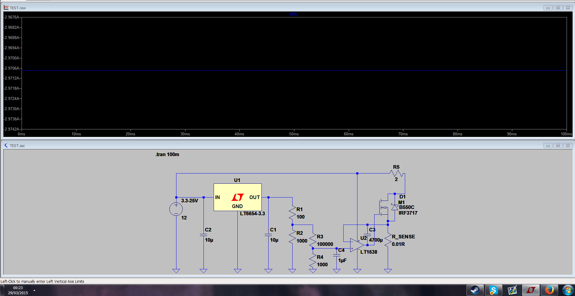
and it works great. I change the resistor divider resistence and it changes the limited current up to 3A. but, as I use the simulation on the resistor it shows me negative current. is it going to be an use? what does this negative current mean? if I would build this in real life and put any load, will the voltage and current be the voltage I set and the current that I set?
 

You've got six resistors, which one are you talking about?
 
  • Like
Reactions: xReM1x

    xReM1x

    Points: 2
    Helpful Answer Positive Rating
Maybe it has to do with the orientation of the resistor? Try rotating it 180 degrees and see if that makes a difference. There's no way current can flow through the resistor towards the supply.
 

Maybe it has to do with the orientation of the resistor? Try rotating it 180 degrees and see if that makes a difference. There's no way current can flow through the resistor towards the supply.
thanks it helped. also, I know its a silly question but is my schematic gonna work? In simulation it works great but I dont know about real life :(
 

I think it should work, but you're going to have to build it and test it. Also, keep in mind that the sense resistor is going to contribute some voltage error (30 mV at 3 Amps); you have to decide if that's ok for your application.
 
  • Like
Reactions: xReM1x

    xReM1x

    Points: 2
    Helpful Answer Positive Rating
I think it should work, but you're going to have to build it and test it. Also, keep in mind that the sense resistor is going to contribute some voltage error (30 mV at 3 Amps); you have to decide if that's ok for your application.
30mV is alright, thanks for your help barry :)
 

thanks it helped. also, I know its a silly question but is my schematic gonna work? In simulation it works great but I dont know about real life :(

It has a number of problems
1) That voltage divider should be simplified. You have two dividers cascaded which makes it more complicated for no reason
2) You're regulating from a very small voltage (30mv) on R_Sense which is not easy in real life.
3) Your 4700uF cap is unreaslitic, at first I assumed it was pF which is 1,000,000X less.
4) You don't need D1. It's not important for operation and the body diode of the mosfet is there anyway
5) The circuit shown is putting 6V*3A=18W though the mosfet. The mosfet you chose cannot do this. You need a TO-220, TO-247, SOT-227 etc and you need a heatsink and probably a fan to sustain the 18W shown or 36W worst case. [EDIT: Just saw you have text indicating up to 25V in. That's 75W worst case which is very serious heat dissipation]
6) Double check the "Safe Operating Area" of any part you chose. Mosfets are limited in the linear regions. Again, the part you picked can't sustain operation in this region (12V @3A)

In regards to 2, it looks like your Amp choice may actually be ok though I'd double check the claims of operation with inputs at the negative rail, which is what you're asking it to do. I'd also increase R_sense to target 100mV at your target current. The more the better as far as circuit control goes. 100mV is still only 1/3W.

In regards to 3 you need to insert a resistor between R_Sense and C3. 1k perhaps, which you can get away with because the input bias currents are only 20nA which means the 1k won't introduce any significant error. Then you should be able to reduce C3 by several orders of magnitude while still hitting the same target bandwidth. Note that you don't need to heavily limit bandwidth. This should be able to operate in the high 100's of KHz pretty easily.
 
  • Like
Reactions: xReM1x

    xReM1x

    Points: 2
    Helpful Answer Positive Rating
It has a number of problems
1) That voltage divider should be simplified. You have two dividers cascaded which makes it more complicated for no reason
2) You're regulating from a very small voltage (30mv) on R_Sense which is not easy in real life.
3) Your 4700uF cap is unreaslitic, at first I assumed it was pF which is 1,000,000X less.
4) You don't need D1. It's not important for operation and the body diode of the mosfet is there anyway
5) The circuit shown is putting 6V*3A=18W though the mosfet. The mosfet you chose cannot do this. You need a TO-220, TO-247, SOT-227 etc and you need a heatsink and probably a fan to sustain the 18W shown or 36W worst case. [EDIT: Just saw you have text indicating up to 25V in. That's 75W worst case which is very serious heat dissipation]
6) Double check the "Safe Operating Area" of any part you chose. Mosfets are limited in the linear regions. Again, the part you picked can't sustain operation in this region (12V @3A)

In regards to 2, it looks like your Amp choice may actually be ok though I'd double check the claims of operation with inputs at the negative rail, which is what you're asking it to do. I'd also increase R_sense to target 100mV at your target current. The more the better as far as circuit control goes. 100mV is still only 1/3W.

In regards to 3 you need to insert a resistor between R_Sense and C3. 1k perhaps, which you can get away with because the input bias currents are only 20nA which means the 1k won't introduce any significant error. Then you should be able to reduce C3 by several orders of magnitude while still hitting the same target bandwidth. Note that you don't need to heavily limit bandwidth. This should be able to operate in the high 100's of KHz pretty easily.
1. the 2 dividers is to get 3V out of 3.3V. as I alerady have low dropout 3.3V regulators its cheaper for me just to divide it to 3V. its just for me when im going to print the schematic.
2.
3. well thats because it started oscillate without the capacitor, and the minimum capacitance I found is ~1000uF. I alerady have 4700uF so why not.
4.its just for the schematic. I'm not going to put diode there as the mosfet alerady have a diode.
5. this mosfet is just for simulation. the mosfet I'm going to use is: RFP12N10L
6. checked.

if I increade R_sense it is going to make me some problems (im the simulation, not sure about real life).
could you show me how to connect the resistor?
 

3) Right but I think either you're mistaking uF for pF, you havn't actually seen a 4700uF cap (that's 4.7mF and will be 1 cubic inch +), or don't quite get what it's doing (this is ok). The cap is just for beedback loop compensation and shouldn't ever need to be in the actual power path which is basically where you put it.
4) ok
5) Won't work. Not unless you clarify your requirements. That part is rated for 80W absolute maximum and if you actually have 25V and 3A that's 75W.
6) Are you sure? You need to check worst case voltage and worse case current. I don't think this hits 25V@3A DC.

What problems does increasing R_sense create? 100mV is not a lot.

The 1k resistor goes between the top of R_sense and the - pin of the opamp. The cap stays between the output of the opamp and the - pin. You'll find you can reduce the cap by several orders of magnitude with this resistor and everything will still be stable.
 
  • Like
Reactions: xReM1x

    xReM1x

    Points: 2
    Helpful Answer Positive Rating
3) Right but I think either you're mistaking uF for pF, you havn't actually seen a 4700uF cap (that's 4.7mF and will be 1 cubic inch +), or don't quite get what it's doing (this is ok). The cap is just for beedback loop compensation and shouldn't ever need to be in the actual power path which is basically where you put it.
4) ok
5) Won't work. Not unless you clarify your requirements. That part is rated for 80W absolute maximum and if you actually have 25V and 3A that's 75W.
6) Are you sure? You need to check worst case voltage and worse case current. I don't think this hits 25V@3A DC.

What problems does increasing R_sense create? 100mV is not a lot.

The 1k resistor goes between the top of R_sense and the - pin of the opamp. The cap stays between the output of the opamp and the - pin. You'll find you can reduce the cap by several orders of magnitude with this resistor and everything will still be stable.
3) no I'm not mistaking uF for pF. I actually seen 4700uF and more caps. I tried the thing that you said with the resistor and it didnt change anything at all..
5) the part is rated for 12A 100V..
6.) yes.
the problem with increasing the resistence is first my ltspice is making problems (dosent simulate it) :
15559618b0c3b7bbc7d2e7b98c3fd93e.png
 

3) Ok. See below
5) But not simultaneously because it's limited to 80W. This mosfet is unusual (these days) in that it doesn't specify additional linear region DC restrictions below the 80W boundary (note that the operating area chart has a typo, what says 60W should be 80W). BUT, 80W is far too close to your 75W theoretical limit and far too much heat to deal with reasonably on a TO-220 package.
6) It's close because of the above. Again, unless you can make assumptions about your load and the wattage it will consume (If your load consumes wattage that's better for your mosfet), you need a new mosfet or a new plan altogether (switching topology). If you stay with a mosfet, I recommend SOT-227 packages.


In terms of the simulation - press "ESC" and it should be fine.

This is exactly what you want to do in terms of the cap:
current-sink_800mA_cropped_1DAC811E-FB5A-8329-C1968BB1021EC8B0.jpg
 
  • Like
Reactions: xReM1x

    xReM1x

    Points: 2
    Helpful Answer Positive Rating
3) Ok. See below
5) But not simultaneously because it's limited to 80W. This mosfet is unusual (these days) in that it doesn't specify additional linear region DC restrictions below the 80W boundary (note that the operating area chart has a typo, what says 60W should be 80W). BUT, 80W is far too close to your 75W theoretical limit and far too much heat to deal with reasonably on a TO-220 package.
6) It's close because of the above. Again, unless you can make assumptions about your load and the wattage it will consume (If your load consumes wattage that's better for your mosfet), you need a new mosfet or a new plan altogether (switching topology). If you stay with a mosfet, I recommend SOT-227 packages.


In terms of the simulation - press "ESC" and it should be fine.

This is exactly what you want to do in terms of the cap:
current-sink_800mA_cropped_1DAC811E-FB5A-8329-C1968BB1021EC8B0.jpg
3) ok thanks it works. I'm going to use 10uF ceramic capcitors, is it ok?
5)ok, I understand. the problem is that I alerady bought and got the mosfet and its on my hands right now. its TO-220. and I have pretty large heatsink. I could add a fan is neccsary. because fan is cheaper for me than a new mosfet.
6) didnt quite understand. my load is going to be variable as this schematic is additon to a power supply, so the input going to be variable. unless I will put the power supply schematic after the current source I dont know what better, im using the LM2576 for power supply.
so my load is going to be anything that I connect. from a small LED to a motor. 1 queastion - I will short out the output, anything is going to explode?
 

3) Try 1uf. It's not that typical to use more than 1uf strictly for signals
5) Mosfets are expensive?

So btw, I've implemented exactly this topology with a heatsinked TO-220. With the largest digi-key heatsink and a fan blowing from 1" away I rated it for a continuous 45W. You can't come close without a fan and I don't think you can sustain 75W.

But ok here is another idea if you don't want a new mosfet: Add thermal protection. Buy a heatsink that can take two TO-220's (many can) and buy a normally open TO-220 thermal switch. Wire it to short the gate to ground when a certain temperature is exceeded and it will shut down the whole supply. This will let you play closer to the margins because you'll have a backup plan. I'd start with 110C switch. If you're clever, you could work a red LED in between the opamp output and the gate (put in 100ohm like the diagram above but then put an LED and R in parallel to that)


Yes, my point is that if you put 75W through an 80W part with poor thermals it will explode.
 
  • Like
Reactions: xReM1x

    xReM1x

    Points: 2
    Helpful Answer Positive Rating
3) Try 1uf. It's not that typical to use more than 1uf strictly for signals
5) Mosfets are expensive?

So btw, I've implemented exactly this topology with a heatsinked TO-220. With the largest digi-key heatsink and a fan blowing from 1" away I rated it for a continuous 45W. You can't come close without a fan and I don't think you can sustain 75W.

But ok here is another idea if you don't want a new mosfet: Add thermal protection. Buy a heatsink that can take two TO-220's (many can) and buy a normally open TO-220 thermal switch. Wire it to short the gate to ground when a certain temperature is exceeded and it will shut down the whole supply. This will let you play closer to the margins because you'll have a backup plan. I'd start with 110C switch. If you're clever, you could work a red LED in between the opamp output and the gate (put in 100ohm like the diagram above but then put an LED and R in parallel to that)


Yes, my point is that if you put 75W through an 80W part with poor thermals it will explode.
3.) im going to use 0.1uF ceramic capacitor. I hope its fine.
5.) well I must have low gate threshold voltage mosfet up to max ~2V and I dont find alot of those. this 1 piece of mosfet cost 3.7$! I might be an idiot and there are other options on ebay but thats what I orderd.

ok, I could add thermostat and make it short gate to ground thats not a problem. actually I might add it. the only thing is I didnt understand is the LED. is it to show me when the theromstat has reached it rated tempture so when it short the gate to ground the positive is the opamp out and and negative is the ground so its indcator led? if yes, than ye why not I will add it just need to get myself a thremostat.
 

Status
Not open for further replies.

Part and Inventory Search

Welcome to EDABoard.com

Sponsor

Back
Top