Continue to Site

Welcome to EDAboard.com

Welcome to our site! EDAboard.com is an international Electronics Discussion Forum focused on EDA software, circuits, schematics, books, theory, papers, asic, pld, 8051, DSP, Network, RF, Analog Design, PCB, Service Manuals... and a whole lot more! To participate you need to register. Registration is free. Click here to register now.

[SOLVED] Transistor to increase current

Status
Not open for further replies.

wizpic

Advanced Member level 3
Joined
May 23, 2004
Messages
789
Helped
108
Reputation
216
Reaction score
72
Trophy points
1,308
Location
London
Activity points
6,358
Hi all
I have a little simple project to control a motor controller which receives a 0-5v signal in to control the speed, If I try to drive it direct from the micro controller the voltage drops slightly or I don't achieve the max volts out
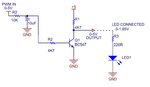
so I thought I'd add a transistor to increase the drive current and add an LED to indicate the voltage by the brightness of it, In the drawing attached is my set up when there is no LED connected I get 0 to 5v out but when I connect the LED I only get a max of 1.8Volts. I may have it completely set up wrong tried some other ways but cant quite get to the bottom of it the more I try the more it gets worse (over trying to find a simple solution.)

Is the drawing correct or the values wrong ??
 

Attachments

  • DRIVER.JPG
    DRIVER.JPG
    32.7 KB · Views: 103

R1 is causing a voltage drop in the output signal. The more current that the transistor pulls, the more voltage drop you will see over R1 and the lower the output voltage will appear. Unfortunately, I don't know exactly what is typically done, but that setup seems like it will always have that voltage drop problem.
 

First, you should get rid of the 10uF cap at the base as well as both resistors at the base. A 1k resistor from the MCU pin to the transistor base should be all you need to drive the transistor using the PWM pin of the MCU. Your cap and resistors are essentially filtering the PWM wave of your MCU and you aren't getting the switching effect you need.

Next, in your circuit, the driver load is actually R1 and you drive the LED by

-connecting R1 to 5v
-the other leg of R1 to the LED anode (LED+)
-finally, the LED cathode to the transistor collector

like so:
https://elinux.org/images/thumb/3/31/EGHS-LEDhigh_output2.jpg/250px-EGHS-LEDhigh_output2.jpg

I wanted to get rid of the PWM with the filter make a smooth 0-5V out and the transistor is just helping to increase the current I can draw from the 5V, I don't just want to switch led on I want a 0-5V output and the led is just there for visual use only, I will try the way you said
 

I see, so your motor controller needs an analog 0-5v and not pwm? Okay sorry, I missed that part at first. In that case filtering the pwm is right, but i think the 10uf cap is too big (depends on how fast you want to change the analog voltage though). I think what you need is somthing to buffer your filtered pwm voltage. Have you tried an opamp buffer?

https://www.gammon.com.au/images/PWM_to_Analog3.png
 
  • Like
Reactions: wizpic

    wizpic

    Points: 2
    Helpful Answer Positive Rating
Thanks for that I had to increase the resistor to the LED to 10K otherwise the voltage would still only increase to 2.2volts give or take a bit, now I get 0-4.8V out which is perfect
 

I wanted to get rid of the PWM with the filter make a smooth 0-5V out and the transistor is just helping to increase the current I can draw from the 5V, I don't just want to switch led on I want a 0-5V output and the led is just there for visual use only.
Motor speed control with PWM is MUCH BETTER than with a variable DC voltage.
Motor speed reduced when its DC voltage is reduced results in a loss of torque. If the motor gets an increased mechanical load then it might stop. Then its voltage must be increased to get it running again. A motor with its speed reduced by PWM receives full voltage pulses so it has lots of torque and does not slow down much when it gets an increased mechanical load. If the load is severe and stops the motor then it starts running at the slow speed when the load is reduced.

Why do you want to feed variable DC from smoothed PWM into a motor controller? This transistor is the motor controller if its current is enough.
 

Op didn't exactly mention that he was using a dc motor, just that his motor controller required an input from 0-5V.
 

Yeah sorry I forgot to add that this is a ready built motor controller 24V 400amp it has B+ & B- M terminal(motor control) turn on signal (24V) and then your control input of 0-5V which I had scope on it and the supply is smooth initial testing was carried out with a pot connected to 5V supply
 

Status
Not open for further replies.

Part and Inventory Search

Welcome to EDABoard.com

Sponsor

Back
Top