Continue to Site

Welcome to EDAboard.com

Welcome to our site! EDAboard.com is an international Electronics Discussion Forum focused on EDA software, circuits, schematics, books, theory, papers, asic, pld, 8051, DSP, Network, RF, Analog Design, PCB, Service Manuals... and a whole lot more! To participate you need to register. Registration is free. Click here to register now.

inverter modified sine wave not work

Status
Not open for further replies.

erchiu

Member level 5
Joined
Apr 7, 2012
Messages
93
Helped
2
Reputation
4
Reaction score
1
Trophy points
1,288
Location
Rome - Italy
Activity points
2,082
hi everyone,
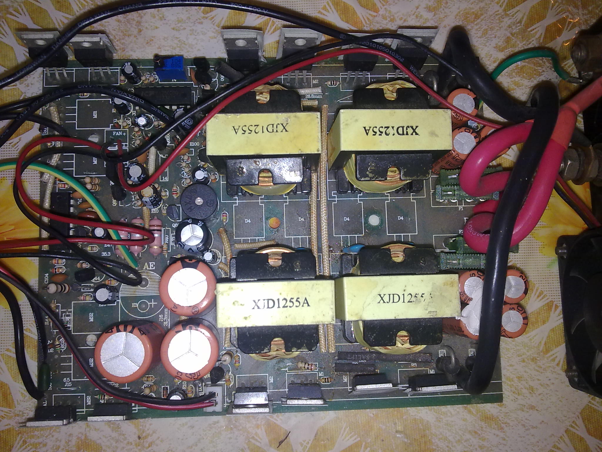
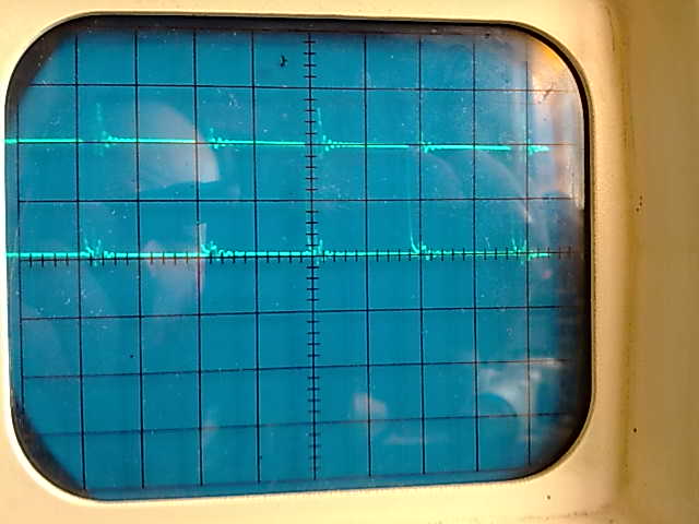
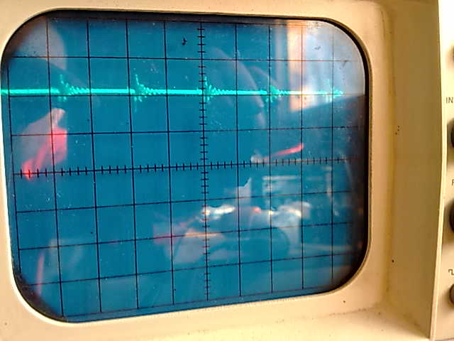
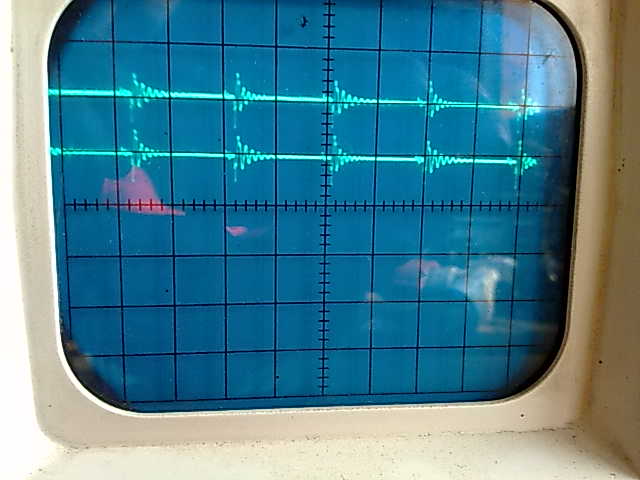
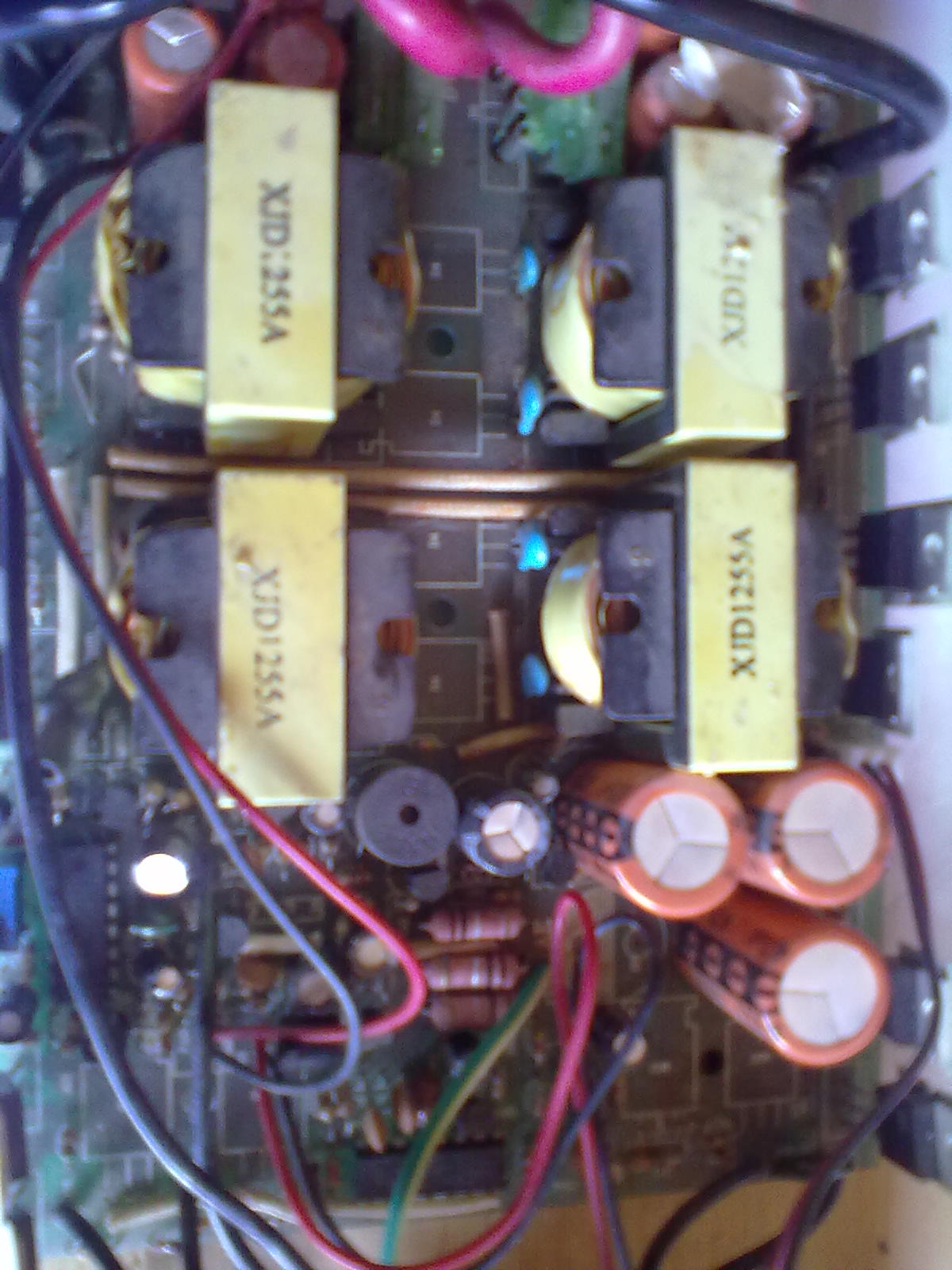
i have an problem with my inverter modified sine wave 12vdc - 220 vac
today it has stopped working and emitting an continued sound.
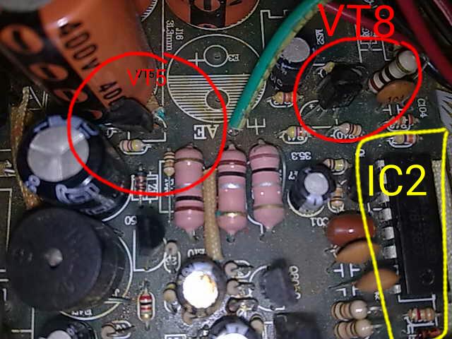
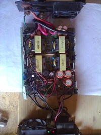
looking the board i not see nothing component burned.
can you give me some suggestion for to continue the check.
on the board there are 8 mosfet irf3205 and 8 sw740,
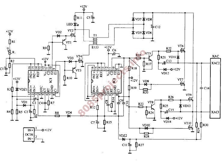
other 2 ka7500bd for the oscillation.


thank you soo much for any help.
erchiu
 

What type of noise are you hearing? Try to explain the noise, hope is it not the humming of a transformer?
 

I'm sorry, maybe i have explained wrong.
The sound that i listen is the buzzer that is turn on continued.
On the out i haven't 220 vac
Thanks
Erchiu
 

First, disconnect the battery and measure the voltage of the battery. Connect the battery back, power the inverter and measure the voltage of the battery.
If you connect the cable that is used to charge the battery, is the buzzer still sounding?
Give me a feedback.
 

The noise you heard is coming out from you buzzer ,what you need to do is to disconnect the supply to 50Hz driver which is 340volt dc and test the dc voltage coming out from the boost converter if its ok then check the second section.
 
  • Like
Reactions: erchiu

    erchiu

    Points: 2
    Helpful Answer Positive Rating
Thank yuo so much for the suggestions.

@ogu reginald

The voltage of the battery is 12.5v before and after the connection to inverter.
The buzzer sound such the battery is low, but is it not so.
The features of this inverter is 11.5v for begin to sound


@kabeer02

I measured the voltage on the three big capacitor that you see on left of the picture and it is zero.
How i do to try the driver section that you speak.
thanks for any helped.
Erchiu
 

I seen and read various article on this inverter type and in one thread i found an schematic as the my inverter.


I found the boost converter but i haven't power out on the capacitor after the rectifier bridge.

i attach one picture where ic ka7500 yellow driver the transformer and in red circle there are 2 pnp (s8050 and s8550 parallel connection).

These pnp are connected on pin 9 of ka7500.

that i not understand is why the ccollectors these pnp in my inverter are connected to vcc? While on the schematic these are connected to ground.

thank you at all for any help
Bye erchiu
 
Last edited:

I found the boost converter but i haven't power out on the capacitor after the rectifier bridge.

This suggests no power is coming through the diode bridge.

Are you getting power from T1?

It's a good idea for you to test the diodes individually (VD5-6-7-8). You may need to clip a lead on each diode, in order to test it out of circuit.
 
  • Like
Reactions: erchiu

    erchiu

    Points: 2
    Helpful Answer Positive Rating
Its a good idea to split the circuit at the C12 point. There could be no volts here because of a short circuit on the output side. This is the most likely failure, one of your output FETS are shorted.
Frank
 
  • Like
Reactions: erchiu

    erchiu

    Points: 2
    Helpful Answer Positive Rating
Thank or much for suggestions.
I checked the output of the transformer and the voltage is zero (before the rectifier bridge).
now i remove the final mosfets and i check one at time
Around on web i found another diagram more near to my inverter but i not fail to attach clearly.
The immage is blurry.
This is the link.
**broken link removed**
I think that this is more similar for the presence of the lm324 and buzzer.
Bye
erchiu
 

I removed all the final mosfets and i found three of these in short circuit.
In this moment i haven't these mosfets.
Can i to leave only those good and to try the inverter with a little load?
Thank you so much
By erchiu

- - - Updated - - -

Ok,
I replaced the three final mosfets broken with other three good.
Now the sistuation is this.
the Buzzer is off, the voltage on the big capacitor is 450v (with a basic tester) but i haven't the output AC voltage
The strange thing is that i not hear the noise of the transformer.
Do you have any idea to go ahead
Thank you
Erchiu
 

I cheked the second circuit part of my inverter and i seen that same this:


In my inverter there are 8 mosfets instead for as in diagram, but a lot of components in this section are same my circuit.
I found vt5 and vt8 (two npn transistors kp44) in output from pin 11 and 8 of the second ka7500b (tl494 on diagram).

As can i check the signal in output on these pins with scope?
Thank you
Erchiu
 

As can i check the signal in output on these pins with scope?
Thank you
Erchiu

Are you using a battery to power your inverter? Then it should be okay to hook up a scope, whether or not the scope is powered from mains AC.

Additionally your scope input needs to be safe to measure hundreds of volts. What is your maximum vertical grid square? 20V? 50V? 100V?

- - - Updated - - -

the Buzzer is off, the voltage on the big capacitor is 450v (with a basic tester) but i haven't the output AC voltage
The strange thing is that i not hear the noise of the transformer.

From what you say, it appears that your high-voltage mosfets failed short circuit.

What about the low-voltage mosfets? Are they operating (switching)? If not, then that would explain why the transformer is silent.

The schematic shows an led between R11 and VT2. Does your unit have this? Does it light at all?

It is important that both IC's work okay. They drive the mosfets. One drives the low-V mosfets. The other drives the high-V mosfets.
There is a chance one or both are ruined. Your scope will tell the story.

You may need to remove an IC, and fabricate your own driver circuit. The basic method might start as a square-wave oscillator.

I believe the low-V side is a very fast frequency.
The high-V side is 50 or 60 Hz.
 
  • Like
Reactions: erchiu

    erchiu

    Points: 2
    Helpful Answer Positive Rating
Hi bradtherad,
I am sorry but i read your post only today.
I try to answer your questions.
I am check the inverter with an single battery (12v) on my workbench.
I have an old scope and the selector have 20 v of max scale, but my probe have an selector x 10
On my inverter there are two leds (one green and one red).
The green is connected to power switch while the red is connected on the one mosfet ir3205 with an pnp s8050.
It is not connect same the diagram!
I measured the signal on pin 9 and 10 of first stadium (ic1) with scope (5 volt scale and 5 uS time base)
The signal is this:


While the output signal on the pin 8 and 10 of second ic (final stage) is the follow:


I can confirm that i do not hear any buzz .
What do you think?
Thank you so much
Erchiu
 

I believe your output IC should have pin 8 high when pin 10 is low. Then they both change state. I think the frequency should be 50 or 60 Hz.

Question: Are you seeing an entire output waveform? What timesweep is your second photograph? Does an entire 50 Hz waveform fit in the screen?
It is the output stage of your inverter, therefore it should be mains frequency.
 
  • Like
Reactions: erchiu

    erchiu

    Points: 2
    Helpful Answer Positive Rating
Today i did another check of the wave form in output from both ic ka7500, using two probes, one for channel.
The scale that i used for all images is 5v and time base is 10 μs.
These are the images of the first IC:
In this case i measured the output signal from pin 10


Now the waveform from pin 10 and pin 9 togheter


The follow images instead show the waveforms from second IC.

This image show the output signal from pin 8 and 11.
The signals are superimposed.


Below I moved one of the two to see them better


What i do not understand is the frequency.

It is the same in the first and in the Second Stage and if I'm not mistaken is 25KHz !!!
 

The follow images instead show the waveforms from second IC.
...
What i do not understand is the frequency.

It is the same in the first and in the Second Stage and if I'm not mistaken is 25KHz !!!

Your output stage does not look as though it is designed to sine PWM at 25 kHz. It looks as though it should operate at 50-60 Hz.

However you say 25 kHz is coming from IC2. There is no obvious reason for this... unless it is coming from IC1, through the wire containing VD4.

This situation is starting to look as IC2 is fried.

To fix the unit, I believe you will need to construct a 50 or 60 Hz oscillating circuit, to drive your output stage. It is a simple substitute for IC2. It will not give you every feature of a commercial unit, however. (Example, you won't have voltage regulation except by doing more work.)

Since low voltage is involved, such an oscillator is a relatively easy project. There is frequent interest in homemade power inverters, like the topology of your schematic.
 

Hi everyone.
I replaced the IC2 with an TL494, mounting it on an 16 dip socket.
Nothing, the result is as before.
I think that on the output pins of IC2 i have a noise of same frequency of first stage, but i not believe there is one oscillation of the Ic.
what do you think?
Erchiu
 

Since you know how to use a TL494, then you know more than I do about control IC's. I have no experience with this type of IC.

As I understand it, the TL494 generates switching signals at high frequency, for the inductor. It tailors its duty cycle according to feedback from the output stage.

However, I'm not sure you need a smart control IC, to generate 50 or 60 Hz, at 50 percent duty cycle.
 
  • Like
Reactions: erchiu

    erchiu

    Points: 2
    Helpful Answer Positive Rating
thank you bradtherad,
I understand what you mean.
for my nature i wanted leave this solution at the last and try to repair the circuit so to understand good the working of this inverter.
I will update you as soon as i have a news
erchiu
 

Status
Not open for further replies.

Similar threads

Part and Inventory Search

Welcome to EDABoard.com

Sponsor

Back
Top