Continue to Site

Welcome to EDAboard.com

Welcome to our site! EDAboard.com is an international Electronics Discussion Forum focused on EDA software, circuits, schematics, books, theory, papers, asic, pld, 8051, DSP, Network, RF, Analog Design, PCB, Service Manuals... and a whole lot more! To participate you need to register. Registration is free. Click here to register now.

[AVR] Help me with led scrolling message board

Status
Not open for further replies.
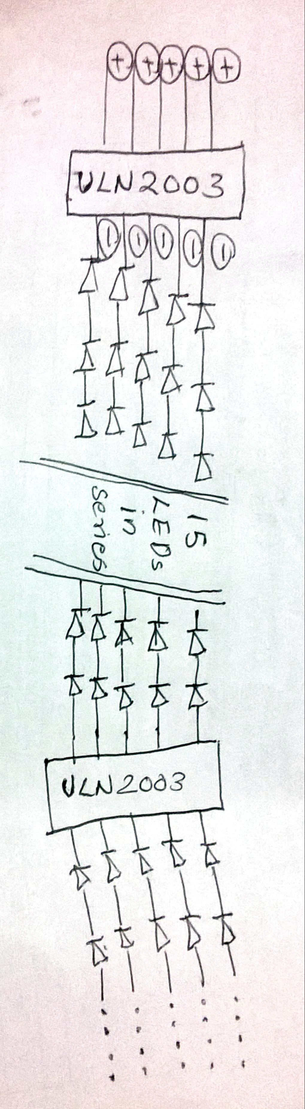
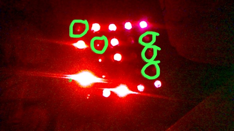
Column multiplexing achieves only 1:100 duty cycle, means 15 mA LED (peak) current translates to 0.15 mA average, helplessly dim.

Try to figure out the basic concept of multiplex displays!
 
Thanks FvM, Can you please suggest the type of MOSFET and its ratings appropriate for my 10X100 LED Matrix. The voltage supplied to the LEDs are 2V via 220ohm resister. I need 15mA for each LED so, for 100 LEDs it is 1500mA ie: 1.5A current.
 

Hi,
I have a doubt, If I am using cascaded shift registers for logic data input all along the columns(100 columns) and another shift register to the rows for scanning (10 rows). When the data is feeded to cascaded shift register at the column. The data is pushed forward to 2nd shift register when the next data is feeded to 1st shift register. Whether this 'forward movement' of the data displays a scrolling effect on the led display? Please help me.
 

shift registers can only display one row at a time .
so you should display all the rows first for a while and then shift every row one step and
scan display again.
while shifting data to cascade shift registers it is not displayed on led's till you give latch pulse to shift registers.

so first you have to understand about shift register limitations and complete functionality then do your job.
One more thing your scanning rate should be minimum 25 frames per seconds as our eye response .
i mean all the rows must be scanned 25 times per second . if your do not follow this you will be face
flickering in your display.(As our tv's and lcd's works)
 
Thanks Irfan Ahmed for your response, Now its clear for me. I should load all the data to the shift register and the do the scanning simultaneously giving a latch pulse to the shift registers. Right. I have one more doubt. I can see two clock input (shift register clock input and storage register clock input). whether these clocks should be same or should be different?
 

Both clocks are different. If you have two HC595 cascaded. Then you have to shift 16 bits by clocking SH_CP and then give one clock to ST_CP to make this 16 bits data appear at the HC595's output.
 
Thanks for the Reply. Then what is OE, Output Enable used for in 74HC595?
 

Thanks for the Reply. Then what is OE, Output Enable used for in 74HC595?

As the name indicates, activating OE, you enable the outputs on the 595 to reflect the status of the different bits in the register. If you deactivate OE, the outputs will be 3-state, or floating.
 
when you give clock and data to the shift registers
it stores data in its entire circuit but do not save it till you no give it latch (ST_CP) signal .
latch also called strobe signal.
next thing OE.
OE means output enable .
you can use this pin to enable output and disable output.
in your project you can use this pin to control brightness of your display .
you can give it high frequency pwm signal to control its brightness according to your PWM.
and if you do not want to use OE or you want to avoid its programming then you can just ground it , it will work .
 

Thanks irfan Ahmad, now its clear for me.

I got a program for scrolling led matrix from internet. The circuit seems similer to mine. But when I tried to complie an error with missing include file 'font5x7.hex' is showing. I don't know where to find this file. Can anybody help me.

Code:
#include <avr/io.h>#include <util/delay.h>#include <avr/interrupt.h>#include <avr/pgmspace.h>#include <string.h>#include "font5x7.h"volatile PGM_P ptr=smallFont;
volatile uint16_t ii,iii;
//Message to displayvolatile char string[]="Welcome ! * Avinash Gupta * ";
volatile uint8_t len;
#define DISP_ROW_CNT 7#define DISP_COL_CNT 15/***************************************Configure Connections****************************************/#define HC595_PORT   PORTB #define HC595_DDR    DDRB#define HC595_DS_POS PB0#define HC595_SH_CP_POS PB1#define HC595_ST_CP_POS PB2/***************************************Configure Connections ***ENDS*******************************************/void HC595Init()
{

   HC595_DDR|=((1<<HC595_SH_CP_POS)|(1<<HC595_ST_CP_POS)|(1<<HC595_DS_POS));
}
#define HC595DataHigh() (HC595_PORT|=(1<<HC595_DS_POS))#define HC595DataLow() (HC595_PORT&=(~(1<<HC595_DS_POS)))void HC595Pulse()
{

   //Pulse the Shift Clock   HC595_PORT|=(1<<HC595_SH_CP_POS);//HIGH   HC595_PORT&=(~(1<<HC595_SH_CP_POS));//LOW}
void HC595Latch()
{

   //Pulse the Store Clock   HC595_PORT|=(1<<HC595_ST_CP_POS);//HIGH   _delay_loop_1(1);
   HC595_PORT&=(~(1<<HC595_ST_CP_POS));//LOW   _delay_loop_1(1);
}
void SelectRow(uint8_t r)
{

   DDRD|=(0B11110111);
   PORTD&=(0B00001000);
   switch(r)
   {

      case6:
         PORTD|=(1<<PD0);
         break;
      case5:
         PORTD|=(1<<PD1);
         break;
      case4:
         PORTD|=(1<<PD2);
         break;
      case3:
         PORTD|=(1<<PD4);
         break;
      case2:
         PORTD|=(1<<PD5);
         break;
      case1:
         PORTD|=(1<<PD6);
         break;
      case0:
         PORTD|=(1<<PD7);
         break;
   }
}
void main()
{

   // Prescaler = FCPU/256   TCCR0|=((1<<CS02));
   //Enable Overflow Interrupt Enable   TIMSK|=(1<<TOIE0);
   //Initialize Counter   TCNT0=0;
   //Enable Global Interrupt   sei();
   //Init Shift Register   HC595Init();
   //Get Length of message   len=strlen(string);
   ii=iii=0;
   while(1)
   {

   }
}
ISR(TIMER0_OVF_vect)
{

   /*   This interrup service routine (ISR)   Updates the displays   */static uint8_t row;
   static uint16_t cnt=0;
   cnt++;
   //Handle Scrollingif(cnt == 29)
   {

      cnt =0;
      ii++;
      if(ii==5)
      {

         ii=0;
         iii++;
         if(iii>len)
            iii=0;
      }
      return;
   }
   //Now Transfer a row of data   int8_t col;
   int8_t chr = iii;
   int8_t m=ii;
   for(col=0;col<DISP_COL_CNT;col++)
   {

      uint8_t data;
      if(m!=5)
      {

         data=pgm_read_byte( ptr + ((string[chr]-' ')*5)+m);
      }
      else      {

         data=0x00;
      }
      if((data & (1<<row)))
         HC595DataHigh();
      else         HC595DataLow();
      HC595Pulse();
      m++;
      if(m==6)
      {

         chr++;
         m=0;
         if(chr >=len)
            chr=0;
      }
   }
   //Acivate a row according to 'row'   SelectRow(row);
   HC595Latch();
   row++;
   if(row==DISP_ROW_CNT)
   {

      //If on last row then come//back to first.      row=0;
   }
 

Help with Circuit for Led Scrolling Matrix

Hi,
I'm trying to built a led scrolling matrix of size 10X100. I am suppose to give 3V and 20mA for each Led. For 100 led in row the total current will be 2A. Since this is huge I'm planning to give a ULN2003 for each set of 15 led likewise for the whole 100 leds. I'm posting the circuit too. Is this a correct way to connect? This will work? please help me.


- - - Updated - - -

The formation of the alphabets are not accurate. A small glow of led are present where it should not be. I'm posting the photo of the same where u can see green markings are what I mentioned here.


Re: Help with Circuit for Led Scrolling Matrix

I don't know (don't remember). Can ULN2003 sink 2A per channel ? I think it can sink 500 mA per channel. I will check the datasheet and reply. You can also try TIP122 or TIP127 transistors.
 

If you want to stick with the ULN2003 for driver then just make ULN2003 in parallel connection to have more output current per channel.So if your requirement 2A is then just connect the 4 uln2003 in parallel before your matrix but other solutions would solve your current requirement problem.Like Power transistor or Nmosfet.
 

You should also be aware of the max total current from the ULN2003 package of 2.5A. There is also a thermal limit to the package, depending of the package type you use. This will again reduce the capability of the drivers.

Beside this, I'm not sure that your calculation of the necessary current is correct. If you time multiplex a display, the max current you need is only what your max drive current of one column is. If you drive 10 LEDs max at the time in one column, your current need is only 10 x 1 LED. If one LED is 20mA, your column driver need to supply only 200mA in average, IF ALL LEDs are lit. If this is the case one ULN2003 driver can bee a column driver, IF it is fast enough for the scanning speed.

Regarding the ghosting you have in your picture, this is coming from timing issues with the scanning. The driver is no fast enough, or you have an overlapping timing between rows / columns. To correct this you need to look at the software and make a small gap between columns, for the drivers to turn off properly. ULN2003 is in nature a darlington driver and due to this relative slow in reaction/switching. Depending on the speed of your matrix, you may change drivers to a more high speed type.
 

Using ULN2003 is simply a bad idea, also according it's large voltage drop.

I also must confess that I don't understand which multiplexing scheme is actually suggested with the schematic snippets in post #32, particularly how a LED series connection is involved.
 

Re: Help with Circuit for Led Scrolling Matrix

Thanks for the reply milan.rajik, can you please explain about TP127 or TP122? I need a requirement of 2A peak. Whether this will be suitable for my requirement?

- - - Updated - - -

Thanks for the reply ud23, I heard using mosfets can solve the issue. But one of my friend didn't reccomend to use mosfets in LED matrix since it has some delay giving the output. I don't know this is right or wrong.
 

Thanks for the reply Gorgon, Sorry that i didn't mention to say the circuit is of Row scanning (Consisting 100 Led not 10). So, 100X20Ma=2A. Since ULN2003 have only a capacity of 500Ma, I thought of using it for 15 leds (15X20Ma=300Ma) like wise for whole 100 leds in series.

I'm a newbie and not much familiar with the program. Could you please check if there is any problem in the program for the ghosting i mentioned.

Code:
#define F_CPU 20000000UL
#include <avr/io.h>
#include <util/delay.h>

/***************************************

Configure Connections

****************************************/

#define HC595_PORT   PORTB
#define HC595_DDR    DDRB

#define HC595_DS_POS PB0      //Data pin (DS) pin location

#define HC595_SH_CP_POS PB1      //Shift Clock (SH_CP) pin location 
#define HC595_ST_CP_POS PB2      //Store Clock (ST_CP) pin location

/***************************************
Configure Connections ***ENDS***
****************************************/

//Initialize HC595 System

void HC595Init()
{
   //Make the Data(DS), Shift clock (SH_CP), Store Clock (ST_CP) lines output
   HC595_DDR|=((1<<HC595_SH_CP_POS)|(1<<HC595_ST_CP_POS)|(1<<HC595_DS_POS));
}


//Low level macros to change data (DS)lines
#define HC595DataHigh() (HC595_PORT|=(1<<HC595_DS_POS))

#define HC595DataLow() (HC595_PORT&=(~(1<<HC595_DS_POS)))

//Sends a clock pulse on SH_CP line
void HC595Pulse()
{
   //Pulse the Shift Clock

   HC595_PORT|=(1<<HC595_SH_CP_POS);//HIGH

   HC595_PORT&=(~(1<<HC595_SH_CP_POS));//LOW

}

//Sends a clock pulse on ST_CP line
void HC595Latch()
{
   //Pulse the Store Clock

   HC595_PORT|=(1<<HC595_ST_CP_POS);//HIGH
   _delay_loop_1(1);

   HC595_PORT&=(~(1<<HC595_ST_CP_POS));//LOW
   _delay_loop_1(1);
}


/*

Main High level function to write a single byte to
Output shift register 74HC595. 

Arguments:
   single byte to write to the 74HC595 IC

Returns:
   NONE

Description:
   The byte is serially transfered to 74HC595
   and then latched. The byte is then available on
   output line Q0 to Q7 of the HC595 IC.

*/
void HC595Write(uint8_t data)
{
   //Send each 8 bits serially

   //Order is MSB first
   for(uint8_t i=0;i<8;i++)
   {

      //Output the data on DS line according to the
      //Value of MSB
      if(data & 0b10000000)
      {
         //MSB is 1 so output high

         HC595DataHigh();
      }
      else
      {
         //MSB is 0 so output high
         HC595DataLow();
      }

      HC595Pulse();  //Pulse the Clock line
      data=data<<1;  //Now bring next bit at MSB position

   }

   //Now all 8 bits have been transferred to shift register
   //Move them to output latch at one
HC595Latch();

   
}

/*

Simple Delay function approx 0.5 seconds

*/

void Wait()
{
   for(uint8_t i=0;i<30;i++)
   {
      _delay_loop_2(0);
   }
}

int main()
{
   uint8_t led_pattern[29]={
                        0b00001110,
                        0b00010001,
                        0b00011111,
                        0b00010001,
                        0b00010001,

                        0b00000000,

						0b00011110,
                        0b00010001,
                        0b00011110,
                        0b00010001,
                        0b00011110,

						0b00000000,

						0b00001110,
                        0b00010001,
                        0b00010000,
                        0b00010001,
                        0b00001110,

						0b00000000,

						0b00011110,
                        0b00010001,
                        0b00010001,
                        0b00010001,
                        0b00011110,

						0b00000000,

						0b00011111,
                        0b00010000,
                        0b00011110,
                        0b00010000,
                        0b00011111,
                       
                     };

   //Initialize HC595 system

   HC595Init();
   DDRA=0xFF;
   PORTA=0;
   int k,j;
   while(1)
   {

///**********i want to get from here  simplified*********


	  for(uint8_t i=0;i<11;i++)
      {
         HC595Write(led_pattern[i]);   //Write the data to HC595
         j=i;
		 if(i>5){ j=i-6;}
		 if(i>11){ j=i-12;}
		 if(i>17){ j=i-18;}
		 if(i>23){ j=i-24;}
		 	 
		 PORTA=(1<<j);
		 _delay_ms(0.2);   


      }


///**********till here*********

   }


}

Yeah, This is not the proper way for scrolling and displaying. I'm really stuck here. The whole Charecters (A,B,C,D,E) scrolls in 1 second. Don't know how to keep a Charecter steady for a second and jump to next character. I'm really trying hard but no use. Any suggestions please. (This code is for my prototype 5X5 led matrix not for 10X100).

- - - Updated - - -

Thnaks for the reply Fvm, Sorry that i didn't mention to say the circuit is of Row scanning (Consisting 100 Led not 10). So, 100X20Ma=2A. Since ULN2003 have only a capacity of 500Ma, I thought of using it for 15 leds (15X20Ma=300Ma) like wise for whole 100 leds in series.

- - - Updated - - -

Thanks for the reply ud23, So, i can use this instead of messy uln2003 series. But i've seen this is for low speed applications. Whether this will cause any problem of delay in Led scrolling?
 

Thanks for the reply Gorgon, Sorry that i didn't mention to say the circuit is of Row scanning (Consisting 100 Led not 10). So, 100X20Ma=2A. Since ULN2003 have only a capacity of 500Ma, I thought of using it for 15 leds (15X20Ma=300Ma) like wise for whole 100 leds in series.

What you could do is to divide the row into groups of 20 columns, and drive each group with a separate driver. Each row is then forked out into 5 drivers, each driving 20 of the 100 LEDs/ columns. This way you only need 400 mA max from each driver.

I see you are bitbanging the serial registers. Please note that you need a minimum clocking speed of 50bps to make a frame rate of 50 frames/second. I would have used a SPI interface if available for this.
 
Status
Not open for further replies.

Part and Inventory Search

Welcome to EDABoard.com

Sponsor

Back
Top