chirag2239
Member level 3
Hi All,
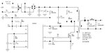
I have a ready design of a power supply circuit and it is 20V,3A. But I need it to be done for 12V,5A. I have a design of transformer too which is for 12V,5A.
My switching frequency is 29KHz and have designed a transformer with the same switching frequency.
Please let me know, do I have to change any components except a transformer? If I have to change any component then please give me a calculation for that and let me know their values.
I am a beginner in SMPS design and I need some standard and unique key formulas to convert one voltage and current value to another voltage and current value.
Please help me as soon as possible.