Continue to Site

Welcome to EDAboard.com

Welcome to our site! EDAboard.com is an international Electronics Discussion Forum focused on EDA software, circuits, schematics, books, theory, papers, asic, pld, 8051, DSP, Network, RF, Analog Design, PCB, Service Manuals... and a whole lot more! To participate you need to register. Registration is free. Click here to register now.

[SOLVED] Numbers with decimals without float

Status
Not open for further replies.
Hello Milan,

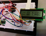
Thanks for your help. I was wondering what's the idea of CopyStr function as it's never called? Interesting to see how this can be made more shorter, but it seems to still not show anything on display. Let me describe what I planned it to do. Read from acceleration sensor X-axis and Z-axis their voltage level which corresponds to acceleration. Calculate it to show g-value eg. 1.66V is 0g and sensitivity is 333mV/g. As the readout from A/D is something like 339.97 which should represent 0.00g on display. Value can be also negative between -3g to +3g and result should be shown on display with 2 digit accuracy. Currently program updates only one axis per cycle. Also on that cycle corresponding highest acceleration value is stored on variable and shown after the actual acceleration. Both axis should have the max acceleration displayed after the actual reading. Like this:
actual max
X=1.25g 2.10
Z=-0.52g 0.45

FVM, Yes, this has evolved quite much, sorry for that. In the beginning I had mcu which ran out of memory and was having problems on using floats so thought to ask help how to overcome without using floats. Changed the mcu to one that has more memory and hoped that would solve the issue. It's not clear to me why this is failing as it's not massive calculations and PIC16F1847 show still much free memory.
 

In your code you had done like this.


Code C - [expand]
1
maxZ = maxZAxis;

I thought you want to copy maxZAxis to maxZ and thats why I made the CopyStr() function which copies one string to another.

What is the value of voltages you get for XAxis and ZAxis to be 0 g ?
 

When on breadboard Z= 1.998V which corresponds to 1g of earths gravity. X = 1.633V which is horizontal and corresponds to 0g. USB seems to now supply 4.763V. So for X= 1.633V/4.763V*2^10 = 351.08 reading from A/D. Every 1 g is 0.333V, so if it's -1g it will be for x 1.633-0.333= 1.300V and max 3g +-0.999V. Once I make that to PCB I need to adjust those constants to match the regulator output. Constants are now ok for the reference voltage usb is supplying on my breadboard..
 

You say Z= 1.998V which corresponds to 1g of earths gravity and you also say that Every 1 g is 0.333V. Which one is right ?

Have you checked this ? https://www.instructables.com/id/Guide-to-gyro-and-accelerometer-with-Arduino-inclu/

Just tell me what is the voltage you get for X value 0 g and what voltage you get for Z value 0 g. Is is linear, the variation of g with voltage ?

- - - Updated - - -

Just provide me the rest values for X and Z.


Try this.


Code C - [expand]
1
2
3
4
5
6
7
8
9
10
11
12
13
14
15
16
17
18
19
20
21
22
23
24
25
26
27
28
29
30
31
32
33
34
35
36
37
38
39
40
41
42
43
44
45
46
47
48
49
50
51
52
53
54
55
56
57
58
59
60
61
62
63
64
65
66
67
68
69
70
71
72
73
74
75
76
77
78
79
80
81
82
83
84
85
86
87
88
89
90
91
92
93
94
95
96
97
98
99
100
101
102
103
104
105
106
107
108
109
110
111
112
113
114
115
116
117
118
119
120
121
122
123
124
125
126
127
128
129
130
131
132
133
134
135
#include "float2ascii.h"
 
// Lcd module connections
sbit LCD_RS at RB4_bit;
sbit LCD_EN at RB5_bit;
sbit LCD_D4 at RB0_bit;
sbit LCD_D5 at RB1_bit;
sbit LCD_D6 at RB2_bit;
sbit LCD_D7 at RB3_bit;
 
sbit LCD_RS_Direction at TRISB4_bit;
sbit LCD_EN_Direction at TRISB5_bit;
sbit LCD_D4_Direction at TRISB0_bit;
sbit LCD_D5_Direction at TRISB1_bit;
sbit LCD_D6_Direction at TRISB2_bit;
sbit LCD_D7_Direction at TRISB3_bit;
 
#define CALIBRATED_0G_Z        368.00   //this is the analog value for the zero G point for Z
#define CALIBRATED_0G_X        349.00   //this is the analog value for the zero G point for X
#define CALIBRATED_SENSITIVITY  59.77   //this number will convert 10bit analog values
                                        //into Gs
char Axis[23];
char maxVal[23];
 
double zMax = 0.0;
double xMax = 0.0;
double gVal = 0.0;
 
 
int i = 0.0;
 
char myStr[23];
double myFloat = 12.3456;
 
void MyDelay(char time) {                // Delay routines
 
      switch(time) {
          case 1:
                delay_us(10);
                break;
          case 2:
                delay_ms(100);
                break;
      };
}
 
double ReadAxis (char channel) {    // Read Axis values from DE-ACCM3D
 
      double analogvalue = 0.0;
 
      analogvalue =  245; //ADC_Read(channel);                       //ADC_Read(channel);  // Read from spesific channel
      MyDelay(1);
      analogvalue += 356; //ADC_Read(channel);                       //ADC_Read(channel);//take an average of 2 readings to reduce noise
      analogvalue /= 2.0;
                                                              //convert analog value into G digits
      if (channel == 1) {
             analogvalue -= CALIBRATED_0G_X;
      }
      if (channel == 2) {
             analogvalue -= CALIBRATED_0G_Z;
      }
      
      analogvalue *= 100.0;                                  // Multiply by 100 to get more resolution before dividing
      analogvalue /= CALIBRATED_SENSITIVITY;
      return analogvalue;
}
 
void main() {
 
      OSCCON = 0b01111010;     // Set internal oscillator to 16mhz
      OSCSTAT = 0b00011001;
      OSCTUNE = 0b00011111;
      
      ADCON1 = 0b10000011;        // Set VREF+ to fixed voltage, fosc/2, A/D right justified
      
      DACCON0.b7 = 0;          // DAC disabled
      
      SRCON0.b7 = 0;           // SR latch disabled
      
      CM1CON0.b7 = 0;          // Disable comparator 1
      CM2CON0.b7 = 0;          // Disable comparator 2
      
      TRISA  = 0b00000110;     //Set RA2 & RA1 as input, others are output
      TRISB  = 0b00000000;     // Set all RB as output
      ANSELA = 0b00000110;     // Set RA1 & RA2 as analog
      ANSELB = 0b00000000;     // Set all B ports as digital
      
      Lcd_Init();              // Initialize Lcd
      Lcd_Cmd(_LCD_CLEAR);
      Lcd_Cmd(_LCD_CURSOR_OFF);
 
      while(1) {                                  // Endless loop
      
 
            if(i == 1) {                          // In one round update only other value
                
                gVal = ReadAxis(1) / 100.0;   // Read X axis
                Float2Ascii(gVal, Axis, 2);   // Put float value to char and 2 decimal
                
                if(gVal > xMax) {             // Update maximum X axial G-force
                      xMax = gVal;
                      Float2Ascii(xMax, maxVal, 2);
                }
                
                gVal = 0;                     // Reset float to release memory. Without this it doesn't work
                Lcd_Out(1,1,Axis);               // Print X axis G-value to first line
                Lcd_out_cp("G ");                 // Add G
                Lcd_Out_cp(maxVal);                 // Print maximum registered X axis G force
            }
            
            //------------Z axis--------------------------------------------------------------------------------------
            
            if(i == 2) {
            
                gVal = ReadAxis(2) / 100.0;   // Read Z Axis
                Float2Ascii(gVal, Axis, 2);
                
                if(gVal > zMax) {
                      zMax = gVal;
                      Float2Ascii(zMax, maxVal, 2);
                }
                
                gVal = 0;
                Lcd_Out(2,1,Axis);               // Print Zaxis G-value to second line
                Lcd_out_cp("G ");
                Lcd_Out_cp(maxVal);                // Print maximum registered Z axis G force
                
                i = 0;
            }
            
            i++;
 
            MyDelay(2);
      }
}

 
Last edited:
Z axis which is vertical axis and the accelerometer is on the table it's affected to 1g and the readout for that is 1.998V. If I turn the accelerometer 90degree it will show 0.333V less equals 1.665V. This is when there is no Z axial forces affecting. So Z 0g is 1.665V and X 0g 1.633V. They have different 0g voltage output but both axes are linear 0.333V/g. Hopefully I was able to explain it properly. Here's the datasheet https://www.dimensionengineering.com/datasheets/DE-ACCM3D.pdf
 

Just an idea:
Code:
typedef struct 
{
	signed int WholeValue;
	unsigned int FractValue
} FloatValue;
 
Try this code.


Code C - [expand]
1
2
3
4
5
6
7
8
9
10
11
12
13
14
15
16
17
18
19
20
21
22
23
24
25
26
27
28
29
30
31
32
33
34
35
36
37
38
39
40
41
42
43
44
45
46
47
48
49
50
51
52
53
54
55
56
57
58
59
60
61
62
63
64
65
66
67
68
69
70
71
72
73
74
75
76
77
78
79
80
81
82
83
84
85
86
87
88
89
90
91
92
93
94
95
96
97
98
99
100
101
102
103
104
105
106
107
108
109
110
111
112
113
114
115
116
117
118
119
120
121
122
123
124
125
126
127
128
129
#include "float2ascii.h"
 
// Lcd module connections
sbit LCD_RS at RB4_bit;
sbit LCD_EN at RB5_bit;
sbit LCD_D4 at RB0_bit;
sbit LCD_D5 at RB1_bit;
sbit LCD_D6 at RB2_bit;
sbit LCD_D7 at RB3_bit;
 
sbit LCD_RS_Direction at TRISB4_bit;
sbit LCD_EN_Direction at TRISB5_bit;
sbit LCD_D4_Direction at TRISB0_bit;
sbit LCD_D5_Direction at TRISB1_bit;
sbit LCD_D6_Direction at TRISB2_bit;
sbit LCD_D7_Direction at TRISB3_bit;
 
#define VREF 5.0
#define CALIBRATED_SENSITIVITY  0.333   //this number will convert 10bit analog values
                                        //into Gs
char Axis[23];
char maxVal[23];
 
double zMax = 0.0;
double xMax = 0.0;
double gVal = 0.0;
 
 
int i = 0.0;
 
char myStr[23];
double myFloat = 12.3456;
 
void MyDelay(char time) {                // Delay routines
 
      switch(time) {
          case 1:
                delay_us(10);
                break;
          case 2:
                delay_ms(100);
                break;
      };
}
 
double ReadAxis (char channel) {    // Read Axis values from DE-ACCM3D
 
      double analogvalue = 0.0;
 
      analogvalue =  ADC_Read(channel);                       //ADC_Read(channel);  // Read from spesific channel
      MyDelay(1);
      analogvalue += ADC_Read(channel);                       //ADC_Read(channel);//take an average of 2 readings to reduce noise
      analogvalue /= 2.0;
                                                              //convert analog value into G digits
      analogvalue = analogValue * VREF / 1023.0;
      analogvalue = analogValue - 1.66;
      analogValue = analogValue / CALIBRATED_SENSITIVITY;
 
      return analogvalue;
}
 
void main() {
 
      OSCCON = 0b01111010;     // Set internal oscillator to 16mhz
      OSCSTAT = 0b00011001;
      OSCTUNE = 0b00011111;
      
      ADCON1 = 0b10000011;        // Set VREF+ to fixed voltage, fosc/2, A/D right justified
      
      DACCON0.b7 = 0;          // DAC disabled
      
      SRCON0.b7 = 0;           // SR latch disabled
      
      CM1CON0.b7 = 0;          // Disable comparator 1
      CM2CON0.b7 = 0;          // Disable comparator 2
      
      TRISA  = 0b00000110;     //Set RA2 & RA1 as input, others are output
      TRISB  = 0b00000000;     // Set all RB as output
      ANSELA = 0b00000110;     // Set RA1 & RA2 as analog
      ANSELB = 0b00000000;     // Set all B ports as digital
      
      Lcd_Init();              // Initialize Lcd
      Lcd_Cmd(_LCD_CLEAR);
      Lcd_Cmd(_LCD_CURSOR_OFF);
 
      while(1) {                                  // Endless loop
      
 
            if(i == 1) {                          // In one round update only other value
                
                gVal = ReadAxis(1);   // Read X axis
                Float2Ascii(gVal, Axis, 2);   // Put float value to char and 2 decimal
                
                if(gVal > xMax) {             // Update maximum X axial G-force
                      xMax = gVal;
                      Float2Ascii(xMax, maxVal, 2);
                }
                
                gVal = 0;                     // Reset float to release memory. Without this it doesn't work
                Lcd_Out(1,1,Axis);               // Print X axis G-value to first line
                Lcd_out_cp("G ");                 // Add G
                Lcd_Out_cp(maxVal);                 // Print maximum registered X axis G force
            }
            
            //------------Z axis--------------------------------------------------------------------------------------
            
            if(i == 2) {
            
                gVal = ReadAxis(2);   // Read Z Axis
                Float2Ascii(gVal, Axis, 2);
                
                if(gVal > zMax) {
                      zMax = gVal;
                      Float2Ascii(zMax, maxVal, 2);
                }
                
                gVal = 0;
                Lcd_Out(2,1,Axis);               // Print Zaxis G-value to second line
                Lcd_out_cp("G ");
                Lcd_Out_cp(maxVal);                // Print maximum registered Z axis G force
                
                i = 0;
            }
            
            i++;
 
            MyDelay(2);
      }
}


- - - Updated - - -

Try this code. I hope it will work.


Code C - [expand]
1
2
3
4
5
6
7
8
9
10
11
12
13
14
15
16
17
18
19
20
21
22
23
24
25
26
27
28
29
30
31
32
33
34
35
36
37
38
39
40
41
42
43
44
45
46
47
48
49
50
51
52
53
54
55
56
57
58
59
60
61
62
63
64
65
66
67
68
69
70
71
72
73
74
75
76
77
78
79
80
81
82
83
84
85
86
87
88
89
90
91
92
93
94
95
96
97
98
99
100
101
102
103
104
105
106
107
108
109
110
111
112
113
114
115
116
117
118
119
120
121
122
123
124
125
126
127
128
129
#include "float2ascii.h"
 
// Lcd module connections
sbit LCD_RS at RB4_bit;
sbit LCD_EN at RB5_bit;
sbit LCD_D4 at RB0_bit;
sbit LCD_D5 at RB1_bit;
sbit LCD_D6 at RB2_bit;
sbit LCD_D7 at RB3_bit;
 
sbit LCD_RS_Direction at TRISB4_bit;
sbit LCD_EN_Direction at TRISB5_bit;
sbit LCD_D4_Direction at TRISB0_bit;
sbit LCD_D5_Direction at TRISB1_bit;
sbit LCD_D6_Direction at TRISB2_bit;
sbit LCD_D7_Direction at TRISB3_bit;
 
#define VREF 5.0
#define CALIBRATED_SENSITIVITY  0.333   //this number will convert 10bit analog values
                                        //into Gs
char Axis[23];
char maxVal[23];
 
double zMax = 0.0;
double xMax = 0.0;
double gVal = 0.0;
 
 
int i = 0.0;
 
char myStr[23];
double myFloat = 12.3456;
 
void MyDelay(char time) {                // Delay routines
 
      switch(time) {
          case 1:
                delay_us(10);
                break;
          case 2:
                delay_ms(100);
                break;
      };
}
 
double ReadAxis (char channel) {    // Read Axis values from DE-ACCM3D
 
      double analogvalue = 0.0;
 
      analogvalue =  ADC_Read(channel);                       //ADC_Read(channel);  // Read from spesific channel
      MyDelay(1);
      analogvalue += ADC_Read(channel);                       //ADC_Read(channel);//take an average of 2 readings to reduce noise
      analogvalue /= 2.0;
                                                              //convert analog value into G digits
      analogvalue = analogValue * 9.091 / 1023.0;
      analogvalue = analogValue - 3;
 
 
      return analogvalue;
}
 
void main() {
 
      OSCCON = 0b01111010;     // Set internal oscillator to 16mhz
      OSCSTAT = 0b00011001;
      OSCTUNE = 0b00011111;
      
      ADCON1 = 0b10000011;        // Set VREF+ to fixed voltage, fosc/2, A/D right justified
      
      DACCON0.b7 = 0;          // DAC disabled
      
      SRCON0.b7 = 0;           // SR latch disabled
      
      CM1CON0.b7 = 0;          // Disable comparator 1
      CM2CON0.b7 = 0;          // Disable comparator 2
      
      TRISA  = 0b00000110;     //Set RA2 & RA1 as input, others are output
      TRISB  = 0b00000000;     // Set all RB as output
      ANSELA = 0b00000110;     // Set RA1 & RA2 as analog
      ANSELB = 0b00000000;     // Set all B ports as digital
      
      Lcd_Init();              // Initialize Lcd
      Lcd_Cmd(_LCD_CLEAR);
      Lcd_Cmd(_LCD_CURSOR_OFF);
 
      while(1) {                                  // Endless loop
      
 
            if(i == 1) {                          // In one round update only other value
                
                gVal = ReadAxis(1);   // Read X axis
                Float2Ascii(gVal, Axis, 2);   // Put float value to char and 2 decimal
                
                if(gVal > xMax) {             // Update maximum X axial G-force
                      xMax = gVal;
                      Float2Ascii(xMax, maxVal, 2);
                }
                
                gVal = 0;                     // Reset float to release memory. Without this it doesn't work
                Lcd_Out(1,1,Axis);               // Print X axis G-value to first line
                Lcd_out_cp("G ");                 // Add G
                Lcd_Out_cp(maxVal);                 // Print maximum registered X axis G force
            }
            
            //------------Z axis--------------------------------------------------------------------------------------
            
            if(i == 2) {
            
                gVal = ReadAxis(2);   // Read Z Axis
                Float2Ascii(gVal, Axis, 2);
                
                if(gVal > zMax) {
                      zMax = gVal;
                      Float2Ascii(zMax, maxVal, 2);
                }
                
                gVal = 0;
                Lcd_Out(2,1,Axis);               // Print Zaxis G-value to second line
                Lcd_out_cp("G ");
                Lcd_Out_cp(maxVal);                // Print maximum registered Z axis G force
                
                i = 0;
            }
            
            i++;
 
            MyDelay(2);
      }
}

 
Incredible, it works. Thank you Milan, you're my hero. :thumbsup:
 

Both codes on post #27. Values are not quite right but at least it's showing something and I can fix the rest by my self..

Few things make me wonder.
1. Why use Double instead of float? Both are same size.
2. Why initialize even int by 0.0 instead of just 0? Isn't int without decimals. Also why do this for double too?
 
Last edited:

It was a mistake. It should be

Code C - [expand]
1
int i = 0;

. I don't know why the Compiler didn't showed error.

double and float have same size in mikroC.

Try this code. i can be char as it doesn't exceed 255.


Code C - [expand]
1
2
3
4
5
6
7
8
9
10
11
12
13
14
15
16
17
18
19
20
21
22
23
24
25
26
27
28
29
30
31
32
33
34
35
36
37
38
39
40
41
42
43
44
45
46
47
48
49
50
51
52
53
54
55
56
57
58
59
60
61
62
63
64
65
66
67
68
69
70
71
72
73
74
75
76
77
78
79
80
81
82
83
84
85
86
87
88
89
90
91
92
93
94
95
96
97
98
99
100
101
102
103
104
105
106
107
108
109
110
111
112
113
114
115
116
117
118
119
120
121
122
#include "float2ascii.h"
 
// Lcd module connections
sbit LCD_RS at RB4_bit;
sbit LCD_EN at RB5_bit;
sbit LCD_D4 at RB0_bit;
sbit LCD_D5 at RB1_bit;
sbit LCD_D6 at RB2_bit;
sbit LCD_D7 at RB3_bit;
 
sbit LCD_RS_Direction at TRISB4_bit;
sbit LCD_EN_Direction at TRISB5_bit;
sbit LCD_D4_Direction at TRISB0_bit;
sbit LCD_D5_Direction at TRISB1_bit;
sbit LCD_D6_Direction at TRISB2_bit;
sbit LCD_D7_Direction at TRISB3_bit;
 
#define VREF 5.0
#define CALIBRATED_SENSITIVITY  0.333   //this number will convert 10bit analog values
                                        //into Gs
char Axis[23];
char maxVal[23];
 
double zMax = 0.0;
double xMax = 0.0;
double gVal = 0.0;
 
 
int i = 0;
 
void MyDelay(char time) {                // Delay routines
 
      switch(time) {
          case 1:
                delay_us(10);
                break;
          case 2:
                delay_ms(100);
                break;
      };
}
 
double ReadAxis (char channel) {    // Read Axis values from DE-ACCM3D
 
      double analogvalue = 0.0;
 
      analogvalue =  ADC_Read(channel);                       //ADC_Read(channel);  // Read from spesific channel
      MyDelay(1);
      analogvalue += ADC_Read(channel);                       //ADC_Read(channel);//take an average of 2 readings to reduce noise
      analogvalue /= 2.0;
       
      return (analogValue * 9.091 / 1023.0) - 3.0;
}
 
void main() {
 
      OSCCON = 0b01111010;     // Set internal oscillator to 16mhz
      OSCSTAT = 0b00011001;
      OSCTUNE = 0b00011111;
      
      ADCON1 = 0b10000011;        // Set VREF+ to fixed voltage, fosc/2, A/D right justified
      
      DACCON0.b7 = 0;          // DAC disabled
      
      SRCON0.b7 = 0;           // SR latch disabled
      
      CM1CON0.b7 = 0;          // Disable comparator 1
      CM2CON0.b7 = 0;          // Disable comparator 2
      
      TRISA  = 0b00000110;     //Set RA2 & RA1 as input, others are output
      TRISB  = 0b00000000;     // Set all RB as output
      ANSELA = 0b00000110;     // Set RA1 & RA2 as analog
      ANSELB = 0b00000000;     // Set all B ports as digital
      
      Lcd_Init();              // Initialize Lcd
      Lcd_Cmd(_LCD_CLEAR);
      Lcd_Cmd(_LCD_CURSOR_OFF);
 
      while(1) {                                  // Endless loop
      
 
            if(i == 1) {                          // In one round update only other value
                
                gVal = ReadAxis(1);   // Read X axis
                Float2Ascii(gVal, Axis, 2);   // Put float value to char and 2 decimal
                
                if(gVal > xMax) {             // Update maximum X axial G-force
                      xMax = gVal;
                      Float2Ascii(xMax, maxVal, 2);
                }
                
                gVal = 0;                     // Reset float to release memory. Without this it doesn't work
                Lcd_Out(1,1,Axis);               // Print X axis G-value to first line
                Lcd_out_cp("G ");                 // Add G
                Lcd_Out_cp(maxVal);                 // Print maximum registered X axis G force
            }
            
            //------------Z axis--------------------------------------------------------------------------------------
            
            if(i == 2) {
            
                gVal = ReadAxis(2);   // Read Z Axis
                Float2Ascii(gVal, Axis, 2);
                
                if(gVal > zMax) {
                      zMax = gVal;
                      Float2Ascii(zMax, maxVal, 2);
                }
                
                gVal = 0;
                Lcd_Out(2,1,Axis);               // Print Zaxis G-value to second line
                Lcd_out_cp("G ");
                Lcd_Out_cp(maxVal);                // Print maximum registered Z axis G force
                
                i = 0;
            }
            
            i++;
 
            MyDelay(2);
      }
}


The calculation was simple.

You sensor gives max 3.33V for 3g and 1.65V for 0g and 0V for -3g and you said that it is linear.

So, If sensor gives 3.33V for one axis then 3.33V = 6g - 3g and for 5V it is 9.xg - 3g.

adcVal * 9.xg / 1023.0 will give 9.xg if adcVal is 1023.0 that is for 5V.
 
Probably there were some issues with my programmer/chip/breadboard as it seems now, whatever I throw to that chip it works. Amazing. I'm soooo happy. Modified the code to actually show the different axis max values as it didn't work right for some reason on that post #27 code. Also zero point for X and Z axis is bit different so I brought back the original calculations. There goes the simplicity, you brought. :oops: What I'm still planning to do is add interrupt for button to reset the maximum values and perhaps pwm for the contrast and button to change it step by step. Then once I receive from China bunch of voltage step up pcb's (2x1.5V AA 3V -> 5V), I'll brew my own PCB and box it. I have few uses for this in my mind already. See what kind of vibrations engine does when running, how much forces can you accelerate/brake etc.
accelerometer.jpg

And here's the code:
Code:
#include "float2ascii.h"

// Lcd module connections
// Channel 1 = X Axis, Channel 2 = Z axis
sbit LCD_RS at RB4_bit;
sbit LCD_EN at RB5_bit;
sbit LCD_D4 at RB0_bit;
sbit LCD_D5 at RB1_bit;
sbit LCD_D6 at RB2_bit;
sbit LCD_D7 at RB3_bit;

sbit LCD_RS_Direction at TRISB4_bit;
sbit LCD_EN_Direction at TRISB5_bit;
sbit LCD_D4_Direction at TRISB0_bit;
sbit LCD_D5_Direction at TRISB1_bit;
sbit LCD_D6_Direction at TRISB2_bit;
sbit LCD_D7_Direction at TRISB3_bit;

#define CALIBRATED_0G_Z        368.00   //this is the analog value for the zero G point for Z
#define CALIBRATED_0G_X        349.00   //this is the analog value for the zero G point for X
#define CALIBRATED_SENSITIVITY  59.77   //this number will convert 10bit analog value
                                        //into Gs
char Axis[23];
char maxValX[23];
char maxValZ[23];

double zMax = 0.0;
double xMax = 0.0;
double gVal = 0.0;
double oldXanalogvalue = 0.0;
double oldZanalogvalue = 0.0;

int temp = 0;

void MyDelay(char time) {                // Delay routines

      switch(time) {
          case 1:
                delay_us(10);
                break;
          case 2:
                delay_ms(100);
                break;
      };
}

double ReadAxis (char channel) {    // Read Axis values from DE-ACCM3D X = 1, Z = 2

      double analogvalue = 0.0;

      analogvalue =  ADC_Read(channel);                        // Read from spesific channel
      MyDelay(1);
      analogvalue += ADC_Read(channel);                       //take an average of 2 readings to reduce noise
      analogvalue /= 2.0;
      if (channel == 1) temp = analogvalue-oldXanalogvalue;
      if (channel == 2) temp = analogvalue-oldZanalogvalue;
      
      if( temp>1 || temp<-1 ) //ignore small changes to make display more readable
      {                                                              //convert analog value into G digits
      if (channel == 1) {
         oldXanalogvalue = analogvalue;
         analogvalue -= CALIBRATED_0G_X;
      }
      if (channel == 2) {
         oldZanalogvalue = analogvalue;
         analogvalue -= CALIBRATED_0G_Z;
      }

      analogvalue *= 100.0;                                  // Multiply by 100 to get more resolution before dividing
      analogvalue /= CALIBRATED_SENSITIVITY;
      return analogvalue;
      } else return 5000;
}

void main() {

      OSCCON = 0b01111010;     // Set internal oscillator to 16mhz
      OSCSTAT = 0b00011001;
      OSCTUNE = 0b00011111;

      ADCON1 = 0b10000011;        // Set VREF+ to fixed voltage, fosc/2, A/D right justified

      DACCON0.b7 = 0;          // DAC disabled

      SRCON0.b7 = 0;           // SR latch disabled

      CM1CON0.b7 = 0;          // Disable comparator 1
      CM2CON0.b7 = 0;          // Disable comparator 2

      TRISA  = 0b00000110;     //Set RA2 & RA1 as input, others are output
      TRISB  = 0b00000000;     // Set all RB as output
      ANSELA = 0b00000110;     // Set RA1 & RA2 as analog
      ANSELB = 0b00000000;     // Set all B ports as digital

      Lcd_Init();              // Initialize Lcd
      Lcd_Cmd(_LCD_CLEAR);
      Lcd_Cmd(_LCD_CURSOR_OFF);

      while(1) {                                  // Endless loop

                gVal = ReadAxis(1);
                if (gVal != 5000)
                {
                gVal = gVal/100;
                Float2Ascii(gVal, Axis, 2);   // Put float value to char and 2 decimal

                if(gVal > xMax) {             // Update maximum X axial G-force
                      xMax = gVal;
                      Float2Ascii(xMax, maxValX, 2);
                }
                gVal = 0;                     // Reset float to release memory. Without this it doesn't work
                Lcd_Out(1,1,"X=");// Print X axis G-value to first line
                Lcd_out_cp(Axis);
                Lcd_out_cp("G ");                 // Add G
                Lcd_Out(1,10, maxValX);                 // Print maximum registered X axis G force
                Lcd_out_cp("Gmx");
                }
                
               MyDelay(2);
            //------------Z axis--------------------------------------------------------------------------------------

                gVal = ReadAxis(2);
                if (gVal != 5000)
                {
                gVal = gVal/100;
                Float2Ascii(gVal, Axis, 2);
                
                if(gVal > zMax) {
                      zMax = gVal;
                      Float2Ascii(zMax, maxValZ, 2);
                }

                gVal = 0;
                Lcd_Out(2,1,"Z=");               // Print Zaxis G-value to second line
                Lcd_out_cp(Axis);
                Lcd_out_cp("G ");
                Lcd_Out(2,10,maxValZ);                // Print maximum registered Z axis G force
                Lcd_out_cp("Gmx");
                }
            MyDelay(2);
      }
}
 

The sensor datasheet showed an example where adc value is converted to voltage and then this voltage is converted to G. I have directly converted adc value to G.
 
Saved few more bytes of RAM.


Code C - [expand]
1
2
3
4
5
6
7
8
9
10
11
12
13
14
15
16
17
18
19
20
21
22
23
24
25
26
27
28
29
30
31
32
33
34
35
36
37
38
39
40
41
42
43
44
45
46
47
48
49
50
51
52
53
54
55
56
57
58
59
60
61
62
63
64
65
66
67
68
69
70
71
72
73
74
75
76
77
78
79
80
81
82
83
84
85
86
87
88
89
90
91
92
93
94
95
96
97
98
99
100
101
102
103
104
105
106
107
108
#include "float2ascii.h"
 
// Lcd module connections
sbit LCD_RS at RB4_bit;
sbit LCD_EN at RB5_bit;
sbit LCD_D4 at RB0_bit;
sbit LCD_D5 at RB1_bit;
sbit LCD_D6 at RB2_bit;
sbit LCD_D7 at RB3_bit;
 
sbit LCD_RS_Direction at TRISB4_bit;
sbit LCD_EN_Direction at TRISB5_bit;
sbit LCD_D4_Direction at TRISB0_bit;
sbit LCD_D5_Direction at TRISB1_bit;
sbit LCD_D6_Direction at TRISB2_bit;
sbit LCD_D7_Direction at TRISB3_bit;
                                        
char strDisplay[10];
 
double zMax = 0.0;
double xMax = 0.0;
double gVal = 0.0;
 
int i = 0;
 
double ReadAxis (char channel) {    // Read Axis values from DE-ACCM3D
 
      char i = 0;
      double analogvalue = 0.0;
    
      while(i < 2) {
      analogvalue += ADC_Read(channel);
      Delay_us(10);
          ++i;
      }
 
      //return ((analogValue / 2.0) * 9.091 / 1023.0) - 3.0;
      return (analogValue / 225.1) - 3.0;
}
 
void main() {
 
      OSCCON = 0b01111010;     
      OSCSTAT = 0b00011001;
      OSCTUNE = 0b00011111;
      
      ADCON1 = 0b10000011;     
      
      DACCON0.b7 = 0;          
      
      SRCON0.b7 = 0;           
      
      CM1CON0.b7 = 0;          
      CM2CON0.b7 = 0;          
      
      TRISA  = 0b00000110;     
      TRISB  = 0b00000000;     
      ANSELA = 0b00000110;     
      ANSELB = 0b00000000;     
      
      Lcd_Init();
      Lcd_Cmd(_LCD_CURSOR_OFF);              
      Lcd_Cmd(_LCD_CLEAR);     
 
      while(1) {                                  
      
 
            if(i == 1) {                          
                
                gVal = ReadAxis(1);   
                Float2Ascii(gVal, strDisplay, 2);   
                
        strcat(strDisplay, "G");
        Lcd_Out(1,1,strDisplay); 
 
                if(gVal > xMax) {             
                      xMax = gVal;
                      Float2Ascii(xMax, strDisplay, 2);
              Lcd_Out_cp(strDisplay);           
                }
                
                gVal = 0;                                
                                
            }
            
                        
            if(i == 2) {
            
                gVal = ReadAxis(2);   
                Float2Ascii(gVal, strDisplay, 2);
                
        strcat(strDisplay, "G");
        Lcd_Out(1,1,strDisplay);
 
                if(gVal > zMax) {
                      zMax = gVal;
                      Float2Ascii(zMax, strDisplay, 2);
              Lcd_Out_cp(strDisplay);
                }
                
                gVal = i = 0;
            }
            
            i++;
 
            Delay_ms(100);
      }
}

 
Last edited:
It seems that

Code C - [expand]
1
char strDisplay[10];

has to be

Code C - [expand]
1
char strDisplay[30];

. It is mentioned in the float2ascii.h file that array length should be atleast 30 bytes.
 
That certainly saves more space. I set that char length to 30 and it seems to stabilize that conversion. I added the interrupt for max reset.
Code:
void interrupt(void){
     if (IOCBF.IOCBF7)
      {
        if(!reset_button) // When reset button is pressed
        {
           zMax = 0.0;
           xMax = 0.0;
           oldZanalogvalue = 0.0;
           oldXanalogvalue = 0.0;
        }
      }
       IOCBF.IOCBF7 = 0;        // Clear interrupt flag
 }

// into the main procedure
      INTCON = 0b11001000;     // Intcon GIE, PEIE and IOCE
      IOCBN.b7 =1;             // Interrupt on B7

I'm not sure is it bug on compiler but I wasn't able to set INTCON.IOCE = 1 as it doesn't recognize that IOCE, so I set the whole INTCON register at once. Also I thought that I would be able to use in interrupt INTCON.IOCF instead of IOCBF.IOCBF7 but it didn't recognize that IOCF. Should it actually?

Also I was wondering, the .hex file size on disk is 14.7kb. ROM size on that chip is 14kb. Compiler is telling 68% free rom and 84% free ram. How could this be possible?
 

As mentioned earlier the .hex file contains checksum, eeprom data etc... which is not a part of ROM data.

Try


Code C - [expand]
1
IOCE_bit = 1;


Connect button to RB0 pin. When button is pressed RB0/INT pin has to go low.


Code C - [expand]
1
2
3
4
5
6
7
8
9
10
11
12
13
14
15
16
17
18
19
20
21
22
23
24
25
26
27
28
29
30
31
32
33
34
35
36
37
38
39
40
41
42
43
44
45
46
47
48
49
50
51
52
53
54
55
56
57
58
59
60
61
62
63
64
65
66
67
68
69
70
71
72
73
74
75
76
77
78
79
80
81
82
83
84
85
86
87
88
89
90
91
92
93
94
95
96
97
98
99
100
101
102
103
104
105
106
107
108
109
110
111
112
113
114
115
116
117
118
119
120
121
122
123
124
125
126
127
128
129
130
131
132
133
134
135
136
137
138
139
140
141
142
143
144
145
146
147
#include "float2ascii.h"
 
// Lcd module connections
sbit LCD_RS at RB4_bit;
sbit LCD_EN at RB5_bit;
sbit LCD_D4 at RB0_bit;
sbit LCD_D5 at RB1_bit;
sbit LCD_D6 at RB2_bit;
sbit LCD_D7 at RB3_bit;
 
sbit LCD_RS_Direction at TRISB4_bit;
sbit LCD_EN_Direction at TRISB5_bit;
sbit LCD_D4_Direction at TRISB0_bit;
sbit LCD_D5_Direction at TRISB1_bit;
sbit LCD_D6_Direction at TRISB2_bit;
sbit LCD_D7_Direction at TRISB3_bit;
 
#define method1
//#define method2
                                        
char strDisplay[10];
 
double zMax = 0.0;
double xMax = 0.0;
double gVal = 0.0;
 
int i = 0;
 
char interruptFlag = 0;
 
void interrupt() {
 
    #ifdef method1
        if(INTF_bit) {  //If button pressed
            interruptFlag = 1;          
        }
    #endif
 
    #ifdef method2
        if((INTF_bit) && (!INTEDG_bit)) {   //If button pressed
            INTEDG_bit = 1;         
        }
        else if((INTF_bit) && (INTEDG_bit)) {   //If button released
            interruptFlag = 1;
            INTEDG_bit = 0;         
        }
    #endif
 
    INTF_bit = 0;
}
 
double ReadAxis (char channel) {    // Read Axis values from DE-ACCM3D
 
      char i = 0;
      double analogvalue = 0.0;
    
      while(i < 2) {
      analogvalue += ADC_Read(channel);
      Delay_us(10);
          ++i;
      }
 
      //return ((analogValue / 2.0) * 9.091 / 1023.0) - 3.0;
      return (analogValue / 225.1) - 3.0;
}
 
void main() {
 
      OSCCON = 0b01111010;     
      OSCSTAT = 0b00011001;
      OSCTUNE = 0b00011111;
      
      ADCON1 = 0b10000011;     
      
      DACCON0 = 0;          
      
      SRCON0 = 0;           
      
      CM1CON0 = 0;          
      CM2CON0 = 0;          
      
      TRISA  = 0b00000110;     
      TRISB  = 0b00000001;     
      ANSELA = 0b00000110;     
      ANSELB = 0b00000000;     
      
      Lcd_Init();
      Lcd_Cmd(_LCD_CURSOR_OFF);              
      Lcd_Cmd(_LCD_CLEAR);     
 
      OPTION_REG = 0b10000000;
      INTCON = 0b11010000;
 
      while(1) {                                  
      
 
        if(interruptFlag) {
 
        zMax = 0.0;
            xMax = 0.0;
            oldZanalogvalue = 0.0;
            oldXanalogvalue = 0.0;
 
        interruptFlag = 0;
            }
 
            if(i == 1) {                          
                
                gVal = ReadAxis(1);   
                Float2Ascii(gVal, strDisplay, 2);   
                
            strcat(strDisplay, "G");
            Lcd_Out(1,1,strDisplay); 
 
                if(gVal > xMax) {             
                      xMax = gVal;
                      Float2Ascii(xMax, strDisplay, 2);
                      Lcd_Out_cp(strDisplay);           
                }
                
                gVal = 0;                                
                                
            }
            
                        
            if(i == 2) {
            
                gVal = ReadAxis(2);   
                Float2Ascii(gVal, strDisplay, 2);
                
            strcat(strDisplay, "G");
            Lcd_Out(1,1,strDisplay);
 
                if(gVal > zMax) {
                      zMax = gVal;
                      Float2Ascii(zMax, strDisplay, 2);
                      Lcd_Out_cp(strDisplay);
                }
                
                gVal = i = 0;
            }
            
            i++;
 
            Delay_ms(100);
      }
}

 
Last edited:
Fixed a small issue with the code. If G was negative and if G was -1.0 and then goes down to -3.0 then max value was not updating. It should show that -1.0 is the max value as -1.0 is greater than -3.0.


Code C - [expand]
1
2
3
4
5
6
7
8
9
10
11
12
13
14
15
16
17
18
19
20
21
22
23
24
25
26
27
28
29
30
31
32
33
34
35
36
37
38
39
40
41
42
43
44
45
46
47
48
49
50
51
52
53
54
55
56
57
58
59
60
61
62
63
64
65
66
67
68
69
70
71
72
73
74
75
76
77
78
79
80
81
82
83
84
85
86
87
88
89
90
91
92
93
94
95
96
97
98
99
100
101
102
103
104
105
106
107
108
#include "float2ascii.h"
 
// Lcd module connections
sbit LCD_RS at RB4_bit;
sbit LCD_EN at RB5_bit;
sbit LCD_D4 at RB0_bit;
sbit LCD_D5 at RB1_bit;
sbit LCD_D6 at RB2_bit;
sbit LCD_D7 at RB3_bit;
 
sbit LCD_RS_Direction at TRISB4_bit;
sbit LCD_EN_Direction at TRISB5_bit;
sbit LCD_D4_Direction at TRISB0_bit;
sbit LCD_D5_Direction at TRISB1_bit;
sbit LCD_D6_Direction at TRISB2_bit;
sbit LCD_D7_Direction at TRISB3_bit;
 
char strDisplay[30];
char unit[] = " G ";
 
double zMax = -3.0;
double xMax = -3.0;
double gVal = 0.0;
 
char i = 0;
 
double ReadAxis(char channel) {    // Read Axis values from DE-ACCM3D
 
      char i = 0;
      double analogvalue = 0.0;
 
      while(i < 2) {
            analogvalue += ADC_Read(channel);
            Delay_us(10);
            ++i;
      }
 
      //return ((analogValue / 2.0) * 9.091 / 1023.0) - 3.0;
      return (analogValue / 225.06) - 3.01;
}
 
void main() {
 
      //OSCCON = 0b01111010;
      //OSCSTAT = 0b00011001;
      //OSCTUNE = 0b00011111;
      
      ADCON1 = 0b10100000;
 
      ANSELA = 0b00000110;
      ANSELB = 0b00000000;
      
      CM1CON0 = 0;
      CM2CON0 = 0;
 
      DACCON0 = 0;
      SRCON0 = 0;
      
      TRISA = 0b00000110;
      TRISB = 0b00000000;
 
      Lcd_Init();
      LCD_Cmd(_LCD_TURN_OFF);
      Lcd_Cmd(_LCD_CURSOR_OFF);
      Lcd_Cmd(_LCD_CLEAR);
      LCD_Cmd(_LCD_TURN_ON);
 
      while(1) {
 
            if(i == 1) {
 
                gVal = ReadAxis(1);
                Float2Ascii(gVal, strDisplay, 2);
                strcat(strDisplay, unit);
                Lcd_Out(1,1,strDisplay);
 
                if(gVal > xMax)xMax = gVal;
                      
                Float2Ascii(xMax, strDisplay, 2);
                strcat(strDisplay, unit);
                Lcd_Out_Cp(strDisplay);
 
                gVal = 0.0;
            }
 
 
            if(i == 2) {
 
                gVal = ReadAxis(2);
                Float2Ascii(gVal, strDisplay, 2);
                strcat(strDisplay, unit);
                Lcd_Out(2,1,strDisplay);
 
                if(gVal > zMax)zMax = gVal;
                      
                Float2Ascii(zMax, strDisplay, 2);
                strcat(strDisplay, unit);
                Lcd_Out_Cp(strDisplay);
                
                gVal = 0.0;
                i = 0;
            }
 
            i++;
 
            Delay_ms(100);
      }
}

 
That INTF_bit example freezes the mcu. Are you sure that's right or should it be IOCF_bit instead? But that's not recognized by the compiler.

edit: ah, ok. Should use RBO as that's defined by option_reg. I have already used RB0 on lcd output was thinking to use another button to toggle maximum negative acceleration.
 
Last edited:

Use INT pin for button. Use a different pin for LCD instead of RB0. You can also use RBIF.
 
Status
Not open for further replies.

Similar threads

Part and Inventory Search

Welcome to EDABoard.com

Sponsor

Back
Top